Hi Leute,

Hab mir vor kurzem ein Arduino UNO mit dem GSM Shield besorgt.
Einige Experimente sind auch schon geglückt, nur beim GSM Shield blick
ich nicht durch.
Die Bibliothek zum versenden einer Test SMS mit SerialemMonitor
funktioniert auch, allerdings möchte ich  bei dig.Eingang eine SMS
versenden ohne den SerialMonitor.
Mein Problem; die Befehle, leider sind die nicht in meinem Buch
beschrieben, also kenne ich diese nicht, was, wann, wo, eingetragen
werden muss.???
Mein Sketch (Baustelle)
-----------------------
#include <GSM.h>

#define PINNUMBER "1234

int tasterPin = 12;
int led1Pin = 11;
int tasterStatus;

GSM gsmAccess;


char remoteNumber[20]= "000111222";
char txtMsg[200]="Test SMS";

void setup()
{
  pinMode(tasterPin, INPUT);
  pinMode(led1Pin, OUTPUT);
}


void loop()
{
   tasterStatus = digitalRead(tasterPin);
  if  (tasterStatus == HIGH)
    GSM_SMS sendSMS;
  else
    digitalWrite(led1Pin, HIGH);
  delay (500);
    digitalWrite(led1Pin, LOW);
  delay (500);
}

void sendSMS();
   GSM_SMS beginSMS(remoteNumber);
   GSM_SMS print(txtMsg);
   GSM_SMS endSMS();
-----

Hoffe ihr könnt mir einwenig auf die srünge helfe.
Danke im voraus...
Angehängte Dateien:
-

akorIoT_BC95_top_text.png
310 KB
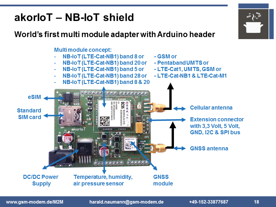
Ich zitiere mal aus dem Quick Start Guide des akorIoT. akoriIoT is ein
Funkadater mit Arduino R3 Header hier:
http://www.gsm-modem.de/M2M/m2m-componets/module-nb-iot-lte-cat-m1-gprs-gps/

"Further code you will write on your own responsibility. The UART for
the cellular module we wired on the same PINs like the origin GSM shield
at Arduino website. Their code will maybe run, but we also detected
mistakes on the code for download at several sources. Free code on the
Internet is just interesting to understand which AT commands were used.
A lot of code examples send an AT command and start a timer to wait and
send the next AT command. This style of coding will work for a quick and
dirty test, but not for IoT devices in mass production. Again, for first
steps and learning the basics an Arduino UNO is fine but for mass
production not. We at akorIoT team use the Arduino UNO to test our radio
adapters and to show that the akorIoT Cx is working. Redesigns for
akorIoT radio adapter to a customised PCB we make most time on some kind
of ARM Cortex M0, M3 or M4 MCU. For that reason, we recommend STM32
Nucleos. Other MCU kits with Arduino header by Microchip, ATMEL, Intel,
Nordic Semiconductor and a lot of more will do the job as well"

"Be aware that you are responsible for your code and your hardware
design. As long you stay with the Arduino UNO you have the freedom to
ask the Arduino community, but you cannot expect to get always the right
answer free of charge. Commercial operating engineering office can not
offer free of charge answers. The hobbyists will maybe do it and help
with free code samples including the free of charge software bugs. If
your application is a commercial application with a budget for
development, then you have the option to ask for HW and SW support with
the akorIoT team. The support is from checking the schematic diagrams,
PCB layout, antenna"

Damit fängt der Ärger an #include <GSM.h> . Die Lib passt eben nur zu
dem GSM Shield von Arduino. In der Lib ist fest gelegt wo TX und RX des
GSM Modul UART ist.Das könnte man im Code ändern. Dann bleibt noch das
Timing und ob die Befehle von einem anderen Modul unterstützt werden.
Wie bereits zitiert sind Libs von Dritten nu gut um die nötigen AT
Befehle zu verstehen. Code sollte am selbst schreiben. Fang mal mit AT
an und warte auf das "okay". Wenn das funktioniert dann ist als nächstes
der Befehl AT+CPIN nötig. Und so geht es dann Schritt für Schritt
weiter.
Bitte melde dich an um einen Beitrag zu schreiben. Anmeldung ist kostenlos und dauert nur eine Minute.
Bestehender Account
Schon ein Account bei Google/GoogleMail? Keine Anmeldung erforderlich!
Mit Google-Account einloggen
Mit Google-Account einloggen
Noch kein Account? Hier anmelden.