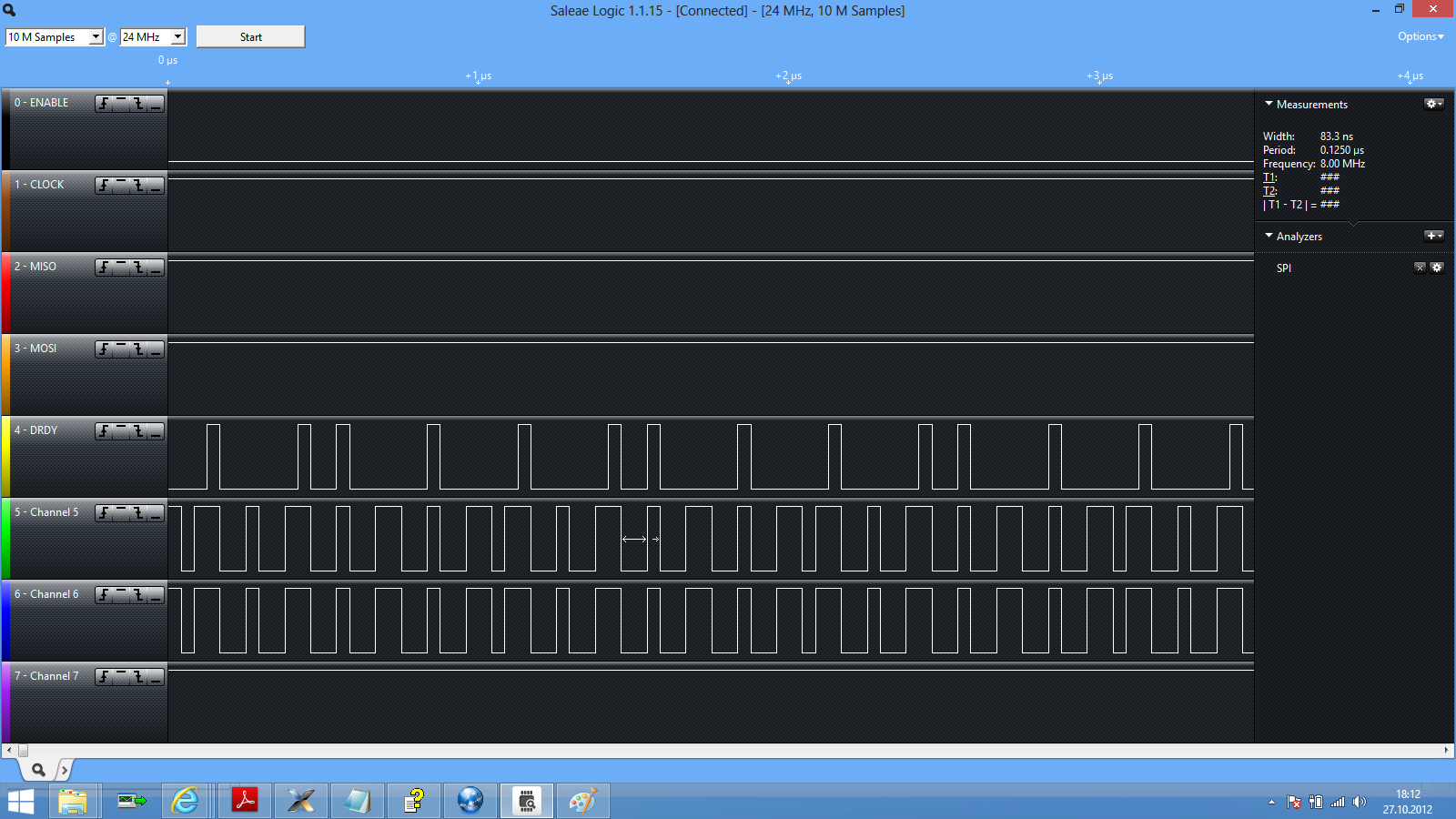
Einen guten Abend!

Versuche meine erste PWM mit dem STM32F4 und leider kommen zwar die
gewünschten 7 MHz raus (wie man das sieht) aber schaut euch mal Channel
5 im Angehängten Bild an. Dazu der Code (in Anlehnung an das Beispiel
der Std. Peripheral Libraries vom STM) und vielleicht kann mir jemand
meinen Fehler sagen:

 //GPIOE Clocks enable
  RCC_AHB1PeriphClockCmd(RCC_AHB1Periph_GPIOE , ENABLE);

  //GPIOE settings
  GPIO_InitStructure2.GPIO_Mode = GPIO_Mode_AF;
  GPIO_InitStructure2.GPIO_Speed = GPIO_Speed_50MHz;
  GPIO_InitStructure2.GPIO_OType = GPIO_OType_PP;
  GPIO_InitStructure2.GPIO_PuPd = GPIO_PuPd_UP ;

  //GPIOE Configuration: Channel 2 as alternate function push-pull
  GPIO_InitStructure2.GPIO_Pin = GPIO_Pin_11 ;
  GPIO_Init(GPIOE, &GPIO_InitStructure2);
  GPIO_PinAFConfig(GPIOE, GPIO_PinSource11, GPIO_AF_TIM1);

  //TIM1 clock enable
  RCC_APB2PeriphClockCmd(RCC_APB2Periph_TIM1 , ENABLE);

  //Time Base configuration
  TIM_TimeBaseStructure.TIM_Prescaler = 0;
  TIM_TimeBaseStructure.TIM_CounterMode = TIM_CounterMode_Up;
  TIM_TimeBaseStructure.TIM_Period = 23;
  TIM_TimeBaseStructure.TIM_ClockDivision = 0;
  TIM_TimeBaseStructure.TIM_RepetitionCounter = 0;

  TIM_TimeBaseInit(TIM1, &TIM_TimeBaseStructure);

  //Channel 2 Configuration in PWM mode
  TIM_OCInitStructure.TIM_OCMode = TIM_OCMode_PWM2;
  TIM_OCInitStructure.TIM_OutputState = TIM_OutputState_Enable;
  TIM_OCInitStructure.TIM_OutputNState = TIM_OutputNState_Enable;
  TIM_OCInitStructure.TIM_Pulse = 11;
  TIM_OCInitStructure.TIM_OCPolarity = TIM_OCPolarity_Low;
  TIM_OCInitStructure.TIM_OCNPolarity = TIM_OCNPolarity_High;
  TIM_OCInitStructure.TIM_OCIdleState = TIM_OCIdleState_Set;
  TIM_OCInitStructure.TIM_OCNIdleState = TIM_OCIdleState_Reset;

  TIM_OC2Init(TIM1, &TIM_OCInitStructure);

  //TIM1 counter enable
  TIM_Cmd(TIM1, ENABLE);

  //TIM1 Main Output Enable
  TIM_CtrlPWMOutputs(TIM1, ENABLE);


Schonmal vielen Dank!!
Angehängte Dateien:
-

logic3.png
96 KB
Ich hab mir deinen Code jetzt nicht genau angeguckt, aber habe hier ein
Example, welches bei mir funktioniert (du musst es nur noch anpassen
bezüglich gewünschtem Port und Frequenz):
1 | #include <stdio.h> |
2 | #include <stdlib.h> |
3 | |
4 | #include "stm32f4xx.h" |
5 | #include "stm32f4xx_gpio.h" |
6 | #include "stm32f4xx_rcc.h" |
7 | #include "stm32f4xx_tim.h" |
8 | |
9 | |
10 | void TIMER_PWM_INIT_EXAMPLE(void) |
11 | {
|
12 | GPIO_InitTypeDef GPIO_InitStructure; |
13 | TIM_TimeBaseInitTypeDef TIM_TimeBaseInitStructure; |
14 | TIM_OCInitTypeDef TIM_OCInitStructure; |
15 | |
16 | // TIM4 clock enable
|
17 | RCC_APB1PeriphClockCmd(RCC_APB1Periph_TIM4, ENABLE); |
18 | |
19 | // GPIOD Clock enable
|
20 | RCC_AHB1PeriphClockCmd(RCC_AHB1Periph_GPIOD, ENABLE); |
21 | |
22 | // GPIO Config
|
23 | GPIO_InitStructure.GPIO_Pin = GPIO_Pin_12|GPIO_Pin_13; |
24 | GPIO_InitStructure.GPIO_Mode = GPIO_Mode_AF; |
25 | GPIO_InitStructure.GPIO_OType = GPIO_OType_PP; |
26 | GPIO_InitStructure.GPIO_Speed = GPIO_Speed_100MHz; |
27 | GPIO_InitStructure.GPIO_PuPd = GPIO_PuPd_NOPULL ; |
28 | GPIO_Init(GPIOD, &GPIO_InitStructure); |
29 | GPIO_PinAFConfig(GPIOD, GPIO_PinSource12, GPIO_AF_TIM4); // Verbindet den Pin12 über die Multiplexerfunktion mit AF2/TIM4 |
30 | GPIO_PinAFConfig(GPIOD, GPIO_PinSource13, GPIO_AF_TIM4); // Verbindet den Pin13 über die Multiplexerfunktion mit AF2/TIM4 |
31 | |
32 | // Timer Config
|
33 | TIM_TimeBaseInitStructure.TIM_ClockDivision = TIM_CKD_DIV1; |
34 | TIM_TimeBaseInitStructure.TIM_CounterMode = TIM_CounterMode_Up; |
35 | TIM_TimeBaseInitStructure.TIM_Period = 0x3FF-1; // 10bit Auflösung der PWM |
36 | TIM_TimeBaseInitStructure.TIM_Prescaler = 100-1; // 84MHz / 100 = 0,84 MHz nach dem Prescaler |
37 | TIM_TimeBaseInitStructure.TIM_RepetitionCounter = 0; |
38 | TIM_TimeBaseInit(TIM4, &TIM_TimeBaseInitStructure); |
39 | |
40 | TIM_OCInitStructure.TIM_OCMode = TIM_OCMode_PWM1; |
41 | TIM_OCInitStructure.TIM_OutputState = TIM_OutputState_Enable; |
42 | TIM_OCInitStructure.TIM_Pulse = 0; |
43 | TIM_OCInitStructure.TIM_OCPolarity = TIM_OCPolarity_High; |
44 | TIM_OC1Init(TIM4, &TIM_OCInitStructure); |
45 | TIM_OC2Init(TIM4, &TIM_OCInitStructure); |
46 | |
47 | TIM_OC1PreloadConfig(TIM4, TIM_OCPreload_Enable); |
48 | TIM_OC2PreloadConfig(TIM4, TIM_OCPreload_Enable); |
49 | |
50 | TIM_ARRPreloadConfig(TIM4, ENABLE); |
51 | TIM_Cmd(TIM4, ENABLE); |
52 | |
53 | TIM4->CCR1 = 0; |
54 | TIM4->CCR2 = 0; |
55 | }
|
56 | |
57 | int main(void) |
58 | {
|
59 | //PLL auf 168MHz konfigurieren
|
60 | SystemInit(); |
61 | |
62 | // PWM INIT
|
63 | TIMER_PWM_INIT_EXAMPLE(); |
64 | |
65 | // Zwei PWM-Outputs setzen
|
66 | TIM4->CCR1 = 500; // LED heller |
67 | TIM4->CCR2 = 10; // LED dunkler |
68 | |
69 | while(1) |
70 | {
|
71 | |
72 | }
|
73 | }
|
Danke dir, ich werde es mal vergleichen, denn ich will schon wissen was
ich falsch gemacht haben... :)
> es mal vergleichen
1 | TIM_OCInitStructure.TIM_Pulse = 11; |
mir ist diese Zeile aufgefallen. Hier habe ich 0 drinn stehen.
Wenn ich das bei mir einstelle, kommt Garnichts mehr raus, also nur Low
Pegel! Komisch!!
Ich denke das sollte der Duty Cycle sein und der soll ja 50 % betragen.
Laut STM wird er folgendermaßen berechnet:
Channel2Pulse = (uint16_t) (((uint32_t)5 * (TimerPeriod - 1)) / 10);

So kam ich auf die 11!
wo setzt du denn dein CCR- Register? Das wird doch sicherlich mit 0x0
initialisiert. Da musst du natürlich noch einen Wert reinschreiben.
achso jetzt verstehe ich: Du setzt dein Duty-Cycle nicht über das
CCR-Register sondern über diese Channel2Pulse-Variable. So habe ich das
noch nie gemacht.

Probier es mal mit dem CCR-Register so wie im Beispiel.
Mit TIM1->CCR2 = 11; ersetzt. Leider genau das gleiche :( Aber danke für
deine Mithilfe!!
Bitte melde dich an um einen Beitrag zu schreiben. Anmeldung ist kostenlos und dauert nur eine Minute.
Bestehender Account
Schon ein Account bei Google/GoogleMail? Keine Anmeldung erforderlich!
Mit Google-Account einloggen
Mit Google-Account einloggen
Noch kein Account? Hier anmelden.