1 | inline void lcd_setRegister(uint16_t regVal, uint16_t datVal){
|
2 | LCD_INST_ADD = regVal;
|
3 | LCD_DATA_ADD = datVal;
|
4 | }
|
5 |
|
6 | inline uint16_t lcd_readRegister(uint16_t regVal){
|
7 | uint16_t data;
|
8 | LCD_INST_ADD = regVal;
|
9 | data = LCD_DATA_ADD;
|
10 | return data;
|
11 | }
|
12 |
|
13 | void lcd_init(){
|
14 | GPIO_InitTypeDef GPIO_InitStructure;
|
15 |
|
16 | // enable clocks for used ports
|
17 | RCC_AHB1PeriphClockCmd(RCC_AHB1Periph_GPIOD | RCC_AHB1Periph_GPIOG | RCC_AHB1Periph_GPIOE | RCC_AHB1Periph_GPIOF, ENABLE);
|
18 | RCC_AHB3PeriphClockCmd(RCC_AHB3Periph_FSMC, ENABLE);
|
19 |
|
20 | //Enable LCD reset pin:
|
21 | GPIO_InitStructure.GPIO_OType = GPIO_OType_PP;
|
22 | GPIO_InitStructure.GPIO_PuPd = GPIO_PuPd_NOPULL;
|
23 | GPIO_InitStructure.GPIO_Mode = GPIO_Mode_OUT;
|
24 | GPIO_InitStructure.GPIO_Speed = GPIO_Speed_100MHz;
|
25 |
|
26 | GPIO_InitStructure.GPIO_Pin = LCD_RES_PIN;
|
27 | GPIO_Init(LCD_CTRL_PORT, &GPIO_InitStructure);
|
28 |
|
29 | // pull reset low during remaining init
|
30 | GPIO_ResetBits(LCD_CTRL_PORT, LCD_RES_PIN);
|
31 |
|
32 | // init FSMC
|
33 | RCC_AHB3PeriphClockCmd(RCC_AHB3Periph_FSMC, ENABLE);
|
34 | GPIO_PinAFConfig(GPIOD, GPIO_PinSource14, GPIO_AF_FSMC);
|
35 | GPIO_PinAFConfig(GPIOD, GPIO_PinSource15, GPIO_AF_FSMC);
|
36 | GPIO_PinAFConfig(GPIOD, GPIO_PinSource0, GPIO_AF_FSMC);
|
37 | GPIO_PinAFConfig(GPIOD, GPIO_PinSource1, GPIO_AF_FSMC);
|
38 | GPIO_PinAFConfig(GPIOD, GPIO_PinSource8, GPIO_AF_FSMC);
|
39 | GPIO_PinAFConfig(GPIOD, GPIO_PinSource9, GPIO_AF_FSMC);
|
40 | GPIO_PinAFConfig(GPIOD, GPIO_PinSource10, GPIO_AF_FSMC);
|
41 | GPIO_PinAFConfig(GPIOD, GPIO_PinSource7, GPIO_AF_FSMC);
|
42 | GPIO_PinAFConfig(GPIOD, GPIO_PinSource11, GPIO_AF_FSMC);
|
43 | GPIO_PinAFConfig(GPIOD, GPIO_PinSource5, GPIO_AF_FSMC);
|
44 | GPIO_PinAFConfig(GPIOD, GPIO_PinSource4, GPIO_AF_FSMC);
|
45 |
|
46 | GPIO_PinAFConfig(GPIOE, GPIO_PinSource7, GPIO_AF_FSMC);
|
47 | GPIO_PinAFConfig(GPIOE, GPIO_PinSource8, GPIO_AF_FSMC);
|
48 | GPIO_PinAFConfig(GPIOE, GPIO_PinSource9, GPIO_AF_FSMC);
|
49 | GPIO_PinAFConfig(GPIOE, GPIO_PinSource10, GPIO_AF_FSMC);
|
50 | GPIO_PinAFConfig(GPIOE, GPIO_PinSource11, GPIO_AF_FSMC);
|
51 | GPIO_PinAFConfig(GPIOE, GPIO_PinSource12, GPIO_AF_FSMC);
|
52 | GPIO_PinAFConfig(GPIOE, GPIO_PinSource13, GPIO_AF_FSMC);
|
53 | GPIO_PinAFConfig(GPIOE, GPIO_PinSource14, GPIO_AF_FSMC);
|
54 | GPIO_PinAFConfig(GPIOE, GPIO_PinSource15, GPIO_AF_FSMC);
|
55 |
|
56 | GPIO_InitStructure.GPIO_Pin = GPIO_Pin_0 | GPIO_Pin_1 | GPIO_Pin_4 | GPIO_Pin_5 | GPIO_Pin_7 | GPIO_Pin_8 | GPIO_Pin_9 | GPIO_Pin_10 | GPIO_Pin_11 | GPIO_Pin_14 | GPIO_Pin_15;
|
57 | GPIO_InitStructure.GPIO_Mode = GPIO_Mode_AF;
|
58 | GPIO_InitStructure.GPIO_Speed = GPIO_Speed_100MHz;
|
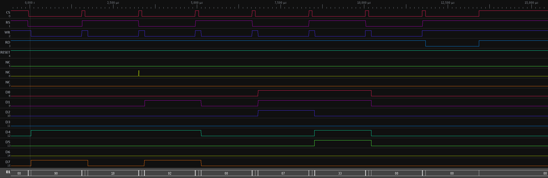
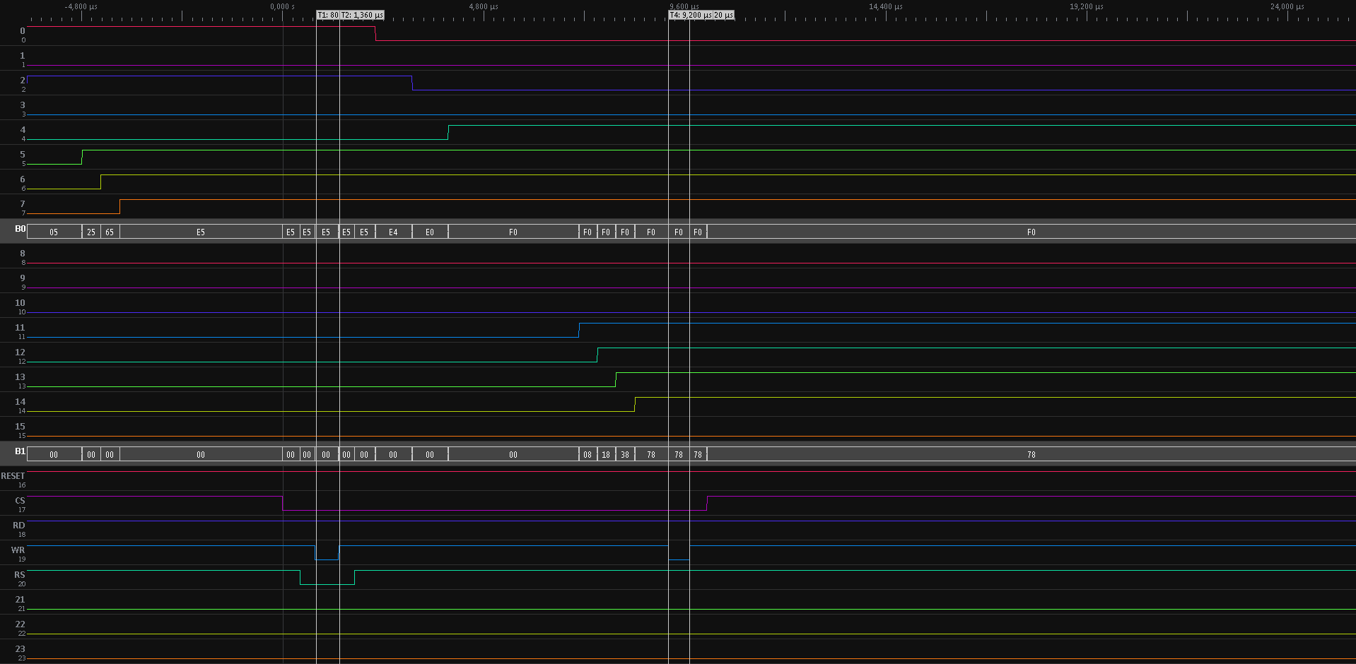
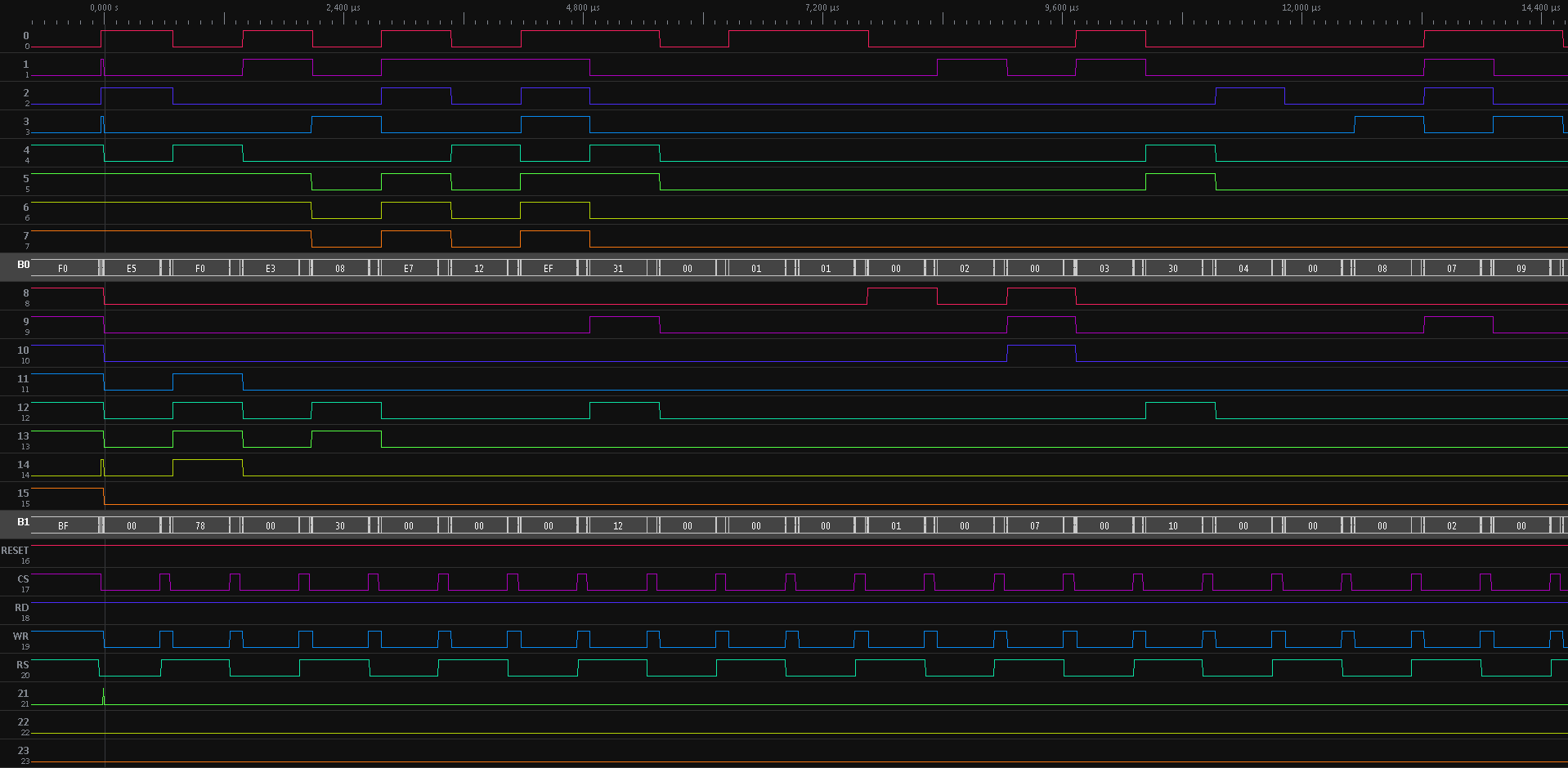
59 | GPIO_InitStructure.GPIO_OType = GPIO_OType_PP;
|
60 | GPIO_InitStructure.GPIO_PuPd = GPIO_PuPd_NOPULL;
|
61 | GPIO_Init(GPIOD, &GPIO_InitStructure);
|
62 |
|
63 | GPIO_InitStructure.GPIO_Pin = GPIO_Pin_7 | GPIO_Pin_8 | GPIO_Pin_9 | GPIO_Pin_10 | GPIO_Pin_11 | GPIO_Pin_12 | GPIO_Pin_13 | GPIO_Pin_14 | GPIO_Pin_15;
|
64 | GPIO_InitStructure.GPIO_Mode = GPIO_Mode_AF;
|
65 | GPIO_InitStructure.GPIO_Speed = GPIO_Speed_100MHz;
|
66 | GPIO_InitStructure.GPIO_OType = GPIO_OType_PP;
|
67 | GPIO_InitStructure.GPIO_PuPd = GPIO_PuPd_NOPULL;
|
68 | GPIO_Init(GPIOE, &GPIO_InitStructure);
|
69 |
|
70 | time_wait(100);
|
71 |
|
72 | FSMC_NORSRAMInitTypeDef FSMC_NORSRAMInitStructure;
|
73 | FSMC_NORSRAMTimingInitTypeDef FSMC_NORSRAMTimingInitStructure;
|
74 |
|
75 | FSMC_NORSRAMInitStructure.FSMC_Bank = FSMC_Bank1_NORSRAM1;
|
76 | FSMC_NORSRAMInitStructure.FSMC_DataAddressMux = FSMC_DataAddressMux_Disable;
|
77 | FSMC_NORSRAMInitStructure.FSMC_MemoryType = FSMC_MemoryType_SRAM;
|
78 | FSMC_NORSRAMInitStructure.FSMC_MemoryDataWidth = FSMC_MemoryDataWidth_16b;
|
79 | FSMC_NORSRAMInitStructure.FSMC_BurstAccessMode = FSMC_BurstAccessMode_Disable;
|
80 | FSMC_NORSRAMInitStructure.FSMC_WaitSignalPolarity = FSMC_WaitSignalPolarity_Low;
|
81 | FSMC_NORSRAMInitStructure.FSMC_WrapMode = FSMC_WrapMode_Disable;
|
82 | FSMC_NORSRAMInitStructure.FSMC_WaitSignalActive = FSMC_WaitSignalActive_BeforeWaitState;
|
83 | FSMC_NORSRAMInitStructure.FSMC_WriteOperation = FSMC_WriteOperation_Enable;
|
84 | FSMC_NORSRAMInitStructure.FSMC_WaitSignal = FSMC_WaitSignal_Disable;
|
85 | FSMC_NORSRAMInitStructure.FSMC_AsynchronousWait = FSMC_AsynchronousWait_Disable;
|
86 | FSMC_NORSRAMInitStructure.FSMC_ExtendedMode = FSMC_ExtendedMode_Disable;
|
87 | FSMC_NORSRAMInitStructure.FSMC_WriteBurst = FSMC_WriteBurst_Enable;//disable
|
88 |
|
89 | FSMC_NORSRAMTimingInitStructure.FSMC_AddressSetupTime = 2; //0
|
90 | FSMC_NORSRAMTimingInitStructure.FSMC_AddressHoldTime = 3; //0
|
91 | FSMC_NORSRAMTimingInitStructure.FSMC_DataSetupTime = 4; //3
|
92 | FSMC_NORSRAMTimingInitStructure.FSMC_BusTurnAroundDuration = 0;
|
93 | FSMC_NORSRAMTimingInitStructure.FSMC_CLKDivision = 1;//1
|
94 | FSMC_NORSRAMTimingInitStructure.FSMC_DataLatency = 0;
|
95 | FSMC_NORSRAMTimingInitStructure.FSMC_AccessMode = FSMC_AccessMode_A;
|
96 |
|
97 | FSMC_NORSRAMInitStructure.FSMC_WriteTimingStruct = &FSMC_NORSRAMTimingInitStructure;
|
98 | FSMC_NORSRAMInit( &FSMC_NORSRAMInitStructure);
|
99 |
|
100 | FSMC_NORSRAMCmd(FSMC_Bank1_NORSRAM1, ENABLE);
|
101 |
|
102 | //pull reset low for at least 1ms
|
103 |
|
104 | //FROM app notes
|
105 | GPIO_SetBits(LCD_CTRL_PORT, LCD_RES_PIN);
|
106 | time_wait(100);
|
107 | GPIO_ResetBits(LCD_CTRL_PORT, LCD_RES_PIN);
|
108 | time_wait(100);
|
109 | GPIO_SetBits(LCD_CTRL_PORT, LCD_RES_PIN);
|
110 |
|
111 | FSMC_NORSRAMCmd(FSMC_Bank1_NORSRAM1, ENABLE);
|
112 | time_wait(5);
|
113 |
|
114 | // Start Initial Sequence
|
115 |
|
116 | lcd_setRegister(0x00E5, 0x78F0); // set SRAM internal timing
|
117 | lcd_setRegister(0x0001, 0x0100); // set SS and SM bit
|
118 | lcd_setRegister(0x0002, 0x0700); // set 1 line inversion
|
119 | lcd_setRegister(0x0003, 0x1030); // set GRAM write direction and BGR=1.
|
120 | lcd_setRegister(0x0004, 0x0000); // Resize register
|
121 | lcd_setRegister(0x0008, 0x0207); // set the back porch and front porch
|
122 | lcd_setRegister(0x0009, 0x0000); // set non-display area refresh cycle ISC[3:0]
|
123 | lcd_setRegister(0x000A, 0x0000); // FMARK function
|
124 | lcd_setRegister(0x000C, 0x0000); // RGB interface setting
|
125 | lcd_setRegister(0x000D, 0x0000); // Frame marker Position
|
126 | lcd_setRegister(0x000F, 0x0000); // RGB interface polarity
|
127 |
|
128 | // Power On sequence
|
129 | lcd_setRegister(0x0010, 0x0000); // SAP, BT[3:0], AP, DSTB, SLP, STB
|
130 | lcd_setRegister(0x0011, 0x0007); // DC1[2:0], DC0[2:0], VC[2:0]
|
131 | lcd_setRegister(0x0012, 0x0000); // VREG1OUT voltage
|
132 | lcd_setRegister(0x0013, 0x0000); // VDV[4:0] for VCOM amplitude
|
133 | lcd_setRegister(0x0007, 0x0001);
|
134 | time_wait(50); // Dis-charge capacitor power voltage
|
135 | lcd_setRegister(0x0010, 0x1090); // 1490//SAP, BT[3:0], AP, DSTB, SLP, STB
|
136 | lcd_setRegister(0x0011, 0x0227); // DC1[2:0], DC0[2:0], VC[2:0]
|
137 | time_wait(50); // Delay 50ms
|
138 | lcd_setRegister(0x0012, 0x001F); //001C// Internal reference voltage= Vci;
|
139 | time_wait(50); // Delay 50ms
|
140 | lcd_setRegister(0x0013, 0x1500); //0x1000//1400 Set VDV[4:0] for VCOM amplitude 1A00
|
141 | lcd_setRegister(0x0029, 0x0027); //0x0012 //001a Set VCM[5:0] for VCOMH //0x0025 0034
|
142 | lcd_setRegister(0x002B, 0x000D); // Set Frame Rate 000C
|
143 | time_wait(50); // Delay 50ms
|
144 | lcd_setRegister(0x0020, 0x0000); // GRAM horizontal Address
|
145 | lcd_setRegister(0x0021, 0x0000); // GRAM Vertical Address
|
146 | // ----------- Adjust the Gamma Curve ----------//
|
147 | lcd_setRegister(0x0030, 0x0000);
|
148 | lcd_setRegister(0x0031, 0x0707);
|
149 | lcd_setRegister(0x0032, 0x0307);
|
150 | lcd_setRegister(0x0035, 0x0200);
|
151 | lcd_setRegister(0x0036, 0x0008);//0207
|
152 | lcd_setRegister(0x0037, 0x0004);//0306
|
153 | lcd_setRegister(0x0038, 0x0000);//0102
|
154 | lcd_setRegister(0x0039, 0x0707);//0707
|
155 | lcd_setRegister(0x003C, 0x0002);//0702
|
156 | lcd_setRegister(0x003D, 0x1D04);//1604
|
157 |
|
158 | //------------------ Set GRAM area ---------------//
|
159 | lcd_setRegister(0x0050, 0x0000); // Horizontal GRAM Start Address
|
160 | lcd_setRegister(0x0051, 0x00EF); // Horizontal GRAM End Address
|
161 | lcd_setRegister(0x0052, 0x0000); // Vertical GRAM Start Address
|
162 | lcd_setRegister(0x0053, 0x013F); // Vertical GRAM Start Address
|
163 | lcd_setRegister(0x0060, 0xA700); // Gate Scan Line
|
164 | lcd_setRegister(0x0061, 0x0001); // NDL,VLE, REV
|
165 | lcd_setRegister(0x006A, 0x0000); // set scrolling line
|
166 | //-------------- Partial Display Control ---------//
|
167 | lcd_setRegister(0x0080, 0x0000);
|
168 | lcd_setRegister(0x0081, 0x0000);
|
169 | lcd_setRegister(0x0082, 0x0000);
|
170 | lcd_setRegister(0x0083, 0x0000);
|
171 | lcd_setRegister(0x0084, 0x0000);
|
172 | lcd_setRegister(0x0085, 0x0000);
|
173 | //-------------- Panel Control -------------------//
|
174 | lcd_setRegister(0x0090, 0x0010);
|
175 | lcd_setRegister(0x0092, 0x0600);
|
176 | lcd_setRegister(0x0007, 0x0133); // 262K color and display ON
|
177 |
|
178 | uint16_t id = lcd_readRegister(0x00);
|
179 |
|
180 | }
|