Hallo zusammen, ich bekomme sehr komische und instabile ADC Werte. Am
ADC Eingang liegt eine Spannung vom Labornetzteil im Bereich 0-3V. Die
Funktion ADC_Config() habe ich aus den FW Beispielen entnommen. Ich habe
viel damit experementiert, Kanaele gewechselt, DMA ein und ausgemacht,
doch leider ohne Erfolg, die ADC Werte wackeln viel zu sehr. IN
stm32f4xx.h ist der HSE Wert auf 8MHz. Hier ist der Code:

void ADC_Config(void)
{
  ADC_InitTypeDef       ADC_InitStructure;
  ADC_CommonInitTypeDef ADC_CommonInitStructure;
  DMA_InitTypeDef       DMA_InitStructure;
  GPIO_InitTypeDef      GPIO_InitStructure;

  /* Enable ADC3, DMA2 and GPIO clocks
****************************************/
  RCC_AHB1PeriphClockCmd(RCC_AHB1Periph_DMA2 | RCC_AHB1Periph_GPIOC,
ENABLE);
  RCC_APB2PeriphClockCmd(RCC_APB2Periph_ADC3, ENABLE);

  /* DMA2 Stream0 channel2 configuration
**************************************/
  DMA_InitStructure.DMA_Channel = DMA_Channel_2;
  DMA_InitStructure.DMA_PeripheralBaseAddr = (uint32_t)&ADC3->DR;
  DMA_InitStructure.DMA_Memory0BaseAddr = (uint32_t)&ADC3ConvertedValue;
  DMA_InitStructure.DMA_DIR = DMA_DIR_PeripheralToMemory;
  DMA_InitStructure.DMA_BufferSize = 1;
  DMA_InitStructure.DMA_PeripheralInc = DMA_PeripheralInc_Disable;
  DMA_InitStructure.DMA_MemoryInc = DMA_MemoryInc_Disable;
  DMA_InitStructure.DMA_PeripheralDataSize =
DMA_PeripheralDataSize_HalfWord;
  DMA_InitStructure.DMA_MemoryDataSize = DMA_MemoryDataSize_HalfWord;
  DMA_InitStructure.DMA_Mode = DMA_Mode_Circular;
  DMA_InitStructure.DMA_Priority = DMA_Priority_High;
  DMA_InitStructure.DMA_FIFOMode = DMA_FIFOMode_Disable;
  DMA_InitStructure.DMA_FIFOThreshold = DMA_FIFOThreshold_HalfFull;
  DMA_InitStructure.DMA_MemoryBurst = DMA_MemoryBurst_Single;
  DMA_InitStructure.DMA_PeripheralBurst = DMA_PeripheralBurst_Single;
  DMA_Init(DMA2_Stream0, &DMA_InitStructure);
  DMA_Cmd(DMA2_Stream0, ENABLE);

  /* Configure ADC3 Channel12 pin as analog input
******************************/
  GPIO_InitStructure.GPIO_Pin = GPIO_Pin_2;
  GPIO_InitStructure.GPIO_Mode = GPIO_Mode_AN;
  GPIO_InitStructure.GPIO_PuPd = GPIO_PuPd_NOPULL ;
  GPIO_Init(GPIOC, &GPIO_InitStructure);

  /* ADC Common Init
**********************************************************/
  ADC_CommonInitStructure.ADC_Mode = ADC_Mode_Independent;
  ADC_CommonInitStructure.ADC_Prescaler = ADC_Prescaler_Div2;
  ADC_CommonInitStructure.ADC_DMAAccessMode =
ADC_DMAAccessMode_Disabled;
  ADC_CommonInitStructure.ADC_TwoSamplingDelay =
ADC_TwoSamplingDelay_5Cycles;
  ADC_CommonInit(&ADC_CommonInitStructure);

  /* ADC3 Init
****************************************************************/
  ADC_InitStructure.ADC_Resolution = ADC_Resolution_12b;
  ADC_InitStructure.ADC_ScanConvMode = DISABLE;
  ADC_InitStructure.ADC_ContinuousConvMode = ENABLE;
  ADC_InitStructure.ADC_ExternalTrigConvEdge =
ADC_ExternalTrigConvEdge_None;
  ADC_InitStructure.ADC_DataAlign = ADC_DataAlign_Right;
  ADC_InitStructure.ADC_NbrOfConversion = 1;
  ADC_Init(ADC3, &ADC_InitStructure);

  /* ADC3 regular channel12 configuration
*************************************/
  ADC_RegularChannelConfig(ADC3, ADC_Channel_12, 1,
    ADC_SampleTime_3Cycles);

 /* Enable DMA request after last transfer (Single-ADC mode) */
  ADC_DMARequestAfterLastTransferCmd(ADC3, ENABLE);

  /* Enable ADC3 DMA */
  ADC_DMACmd(ADC3, ENABLE);

  /* Enable ADC3 */
  ADC_Cmd(ADC3, ENABLE);

  ADC_SoftwareStartConv(ADC3);

}

int main(void)
{
  ADC_Config();

  while(1){
  }
}


Hat Jemand irgendeine Idee warum die ADC Werte sehr instabil sind?
Vielen Dank!

Ilya
Was bedeutet sehr instabil? Nenne mal ein paar Werte.

Wie lange ist das Kabel von Netzteil zu STM32?
Zum Testen empfehle ich einen Widerstandsteiler mit Kondensator von ADC
zu GND und kurze Kabel.
Angehängte Dateien:
-

test.jpg
300 KB
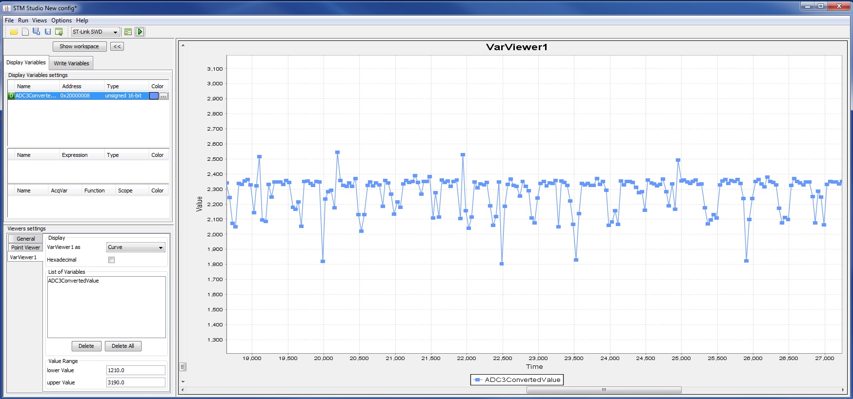
Vielen Dank fuer die Antwort. Im Anhang findest du das aufgenommene ADC
Signal. Die Kabel sind ca. ein Meter lang und vor dem ADC Eingang habe
ich einen OPA + Spannungsfolger + RC Tiefpass. Die analoge Aufbereitung
funktioniert gut und ist stabil. Ich denke, es muss an dem uC liegen.
Irgendeine Idee?
Sieh dir mal die Application Note AN4073 von STM an. Da steht, dass die
Werte des ADCs schwanken und man mit Mittelwerten arbeiten soll.

Gruß Paul
Beobachtest du die Schwankungen auch mit einer Oszi-Messung am
ADC-Eingang?
Sample -time 3cycles? kommt mir sehr wenig vor. Kalibration findet in
deinem Code auch nicht statt. Ich hab's folgendermassen initialisiert:

/* DMA1 channel1 configuration
----------------------------------------------*/
  DMA_DeInit(DMA1_Channel1);
  DMA_InitStructure.DMA_PeripheralBaseAddr = ADC1_DR_Address;
  DMA_InitStructure.DMA_MemoryBaseAddr = (u32)ADC_buf_wr_ptr;
  DMA_InitStructure.DMA_DIR = DMA_DIR_PeripheralSRC;
  DMA_InitStructure.DMA_BufferSize = 12;
  DMA_InitStructure.DMA_PeripheralInc = DMA_PeripheralInc_Disable;
  DMA_InitStructure.DMA_MemoryInc = DMA_MemoryInc_Enable;
  DMA_InitStructure.DMA_PeripheralDataSize =
DMA_PeripheralDataSize_HalfWord;
  DMA_InitStructure.DMA_MemoryDataSize = DMA_MemoryDataSize_HalfWord;
  DMA_InitStructure.DMA_Mode = DMA_Mode_Normal;
//  DMA_InitStructure.DMA_Mode = DMA_Mode_Normal;
  DMA_InitStructure.DMA_Priority = DMA_Priority_VeryHigh;
  DMA_InitStructure.DMA_M2M = DMA_M2M_Disable;
  DMA_Init(DMA1_Channel1, &DMA_InitStructure);
  /* Enable DMA1 channel1 */


  /* ADC1 configuration
------------------------------------------------------*/
  ADC_DeInit( ADC1);
  ADC_InitStructure.ADC_Mode = ADC_Mode_Independent;
  ADC_InitStructure.ADC_ScanConvMode = ENABLE;
  ADC_InitStructure.ADC_ContinuousConvMode = DISABLE;
  //ADC_InitStructure.ADC_ExternalTrigConv = ADC_ExternalTrigConv_None;
  ADC_InitStructure.ADC_ExternalTrigConv = ADC_ExternalTrigConv_T4_CC4;
  ADC_InitStructure.ADC_DataAlign = ADC_DataAlign_Right;
  ADC_InitStructure.ADC_NbrOfChannel = 12;
  ADC_Init(ADC1, &ADC_InitStructure);
  /* ADC1 regular channel14 configuration */
  ADC_RegularChannelConfig(ADC1, ADC_Channel_10, 11,
ADC_SampleTime_28Cycles5);
  ADC_RegularChannelConfig(ADC1, ADC_Channel_11, 12,
ADC_SampleTime_28Cycles5);
  ADC_RegularChannelConfig(ADC1, ADC_Channel_12, 5,
ADC_SampleTime_28Cycles5);
  ADC_RegularChannelConfig(ADC1, ADC_Channel_13, 6,
ADC_SampleTime_28Cycles5);
  ADC_RegularChannelConfig(ADC1, ADC_Channel_0, 1,
ADC_SampleTime_28Cycles5);
  ADC_RegularChannelConfig(ADC1, ADC_Channel_1, 2,
ADC_SampleTime_28Cycles5);
  ADC_RegularChannelConfig(ADC1, ADC_Channel_2, 3,
ADC_SampleTime_28Cycles5);
  ADC_RegularChannelConfig(ADC1, ADC_Channel_3, 4,
ADC_SampleTime_28Cycles5);
  ADC_RegularChannelConfig(ADC1, ADC_Channel_6, 7,
ADC_SampleTime_28Cycles5);
  ADC_RegularChannelConfig(ADC1, ADC_Channel_7, 8,
ADC_SampleTime_28Cycles5);
  ADC_RegularChannelConfig(ADC1, ADC_Channel_8, 9,
ADC_SampleTime_28Cycles5);
  ADC_RegularChannelConfig(ADC1, ADC_Channel_9, 10,
ADC_SampleTime_28Cycles5);
  /* Enable ADC1 DMA */
  ADC_DMACmd(ADC1, ENABLE);
 //ADC_ITConfig(ADC1, ADC_IT_EOC, ENABLE);
  /* Enable ADC1 */
  ADC_Cmd(ADC1, ENABLE);

 /* Enable ADC1 reset calibaration register */
  ADC_ResetCalibration(ADC1);
  /* Check the end of ADC1 reset calibration register */
  while(ADC_GetResetCalibrationStatus(ADC1));
  /* Start ADC1 calibaration */
  ADC_StartCalibration(ADC1);
  /* Check the end of ADC1 calibration */
  while(ADC_GetCalibrationStatus(ADC1));
  /* Enable ADC1 reset calibaration register */
Bitte melde dich an um einen Beitrag zu schreiben. Anmeldung ist kostenlos und dauert nur eine Minute.
Bestehender Account
Schon ein Account bei Google/GoogleMail? Keine Anmeldung erforderlich!
Mit Google-Account einloggen
Mit Google-Account einloggen
Noch kein Account? Hier anmelden.