QO-100 der erste geostationäre Amateurfunkumsetzer
English version of this article follows below
Dieser Artikel soll vor allem eine systematische Übersicht zum Thema darstellen, einzelne Projekte bitte in anderen Artikeln oder im Forum unterbringen.
Durch günstige Umstände (ein hochrangiger Politiker des Staates Qatar ist Funkamateur) wurde auf dem TV-Satelliten Es'Hail-2 auch eine kleine Amateurfunk-Nutzlast untergebracht. Der Satellit einschließlich des Umsetzers wurde in Japan von Mitsubishi gebaut und im November 2018 von SpaceX auf seine geostationäre Position transportiert, etwa drei Erddurchmesser senkrecht über dem Äquator. Seit Februar 2019 ist der Amateurfunkumsetzer nutzbar. Wikipedia-Artikel dazu
Erster Einstieg über Webradio
BATC-Webempfänger Cornwall IO70JB für Breit- und Schmalband
Dolianova auf Sardinien (JM49OJ)
Belgien (JO21FB)
Brasilien (GG56TV)
Südafrika (KG43AR)
Russland (KO92SO)
Russland (KO91OH)
Schmalband-Empfang
Empfangsantenne
Für den Empfang ist eine übliche Satellitenschüssel geeignet. Ein Durchmesser von 60cm reicht aus, aber 80-90cm bieten mehr Reserve. Exotischere Antennenformen wie Hornantennen wären auch denkbar. An der Schüssel wird wie üblich ein LNB (low-noise-block) angebracht. Zum LNB unten mehr.
Ein größerer Durchmesser bringt für den Empfang wenig, die Kurve für den Rauschabstand geht bald asymptotisch in eine Horizontale über.
Anders sieht es für den Sender aus, hier ersetzt ein größerer Durchmesser fehlende Sendeleistung. Einfach beschaffbar sind noch Offset-Schüsseln bis 2,40m Durchmesser. Beispiel: OP240L bestehend aus zwei Halbschalen mit 1,20*2,40m Der Transport dürfte nicht ganz billig sein. Im Vergleich zu 125cm ist der Gewinn um 6,3dB höher, entsprechend einer vierfach höheren Sendeleistung - bei kleinerem Öffnungswinkel und höheren Anforderungen für Befestigung und Ausrichtung.
Man kann dieselbe Schüssel auch zum Senden verwenden, dazu werden mehrere "Dual-Band"-Antennenspeisungen angeboten, siehe unten.
Durch die niedrigere Sendefrequenz ist auch die Ausrichtung dafür einfacher, der Öffnungswinkel ist größer.
Ausrichten der Antenne
Die Antennenrichtung und Drehung des LNB (ein paar Grad abweichend von der senkrechten Montage!) für den eigenen Standort kann man hier berechnen lassen:
Satlex.de Rechner für Azimut- und Elevationswinkel für 25,8° Ost
Die erforderliche Genauigkeit hängt vom Schüsseldurchmesser ab. Ein billiger "Satellitenfinder" hilft nicht, da die Empfangsfeldstärke viel geringer ist als z.B. von Astra 19,2°Ost. Ein RTL-SDR kann die Breitbandbake im Spektrum darstellen, damit lässt sich die Antenne auf Maximum ausrichten.
Hier Lyngsat-Eshail-2 sind die vom Satelliten übertragenen TV-Kanäle aufgelistet. Leider ist deren Antennenkeule auf Nordafrika ausgerichtet, in Europa dürfte davon zu wenig Feldstärke ankommen, um sie anzupeilen.
Zur Bestimmung der horizontalen Richtung kann man einen Kompass benutzen, der allerdings von Metallteilen in der näheren Umgebung beeinflusst wird. Genauer ist ein Satellitenbild des Standorts von Google-Earth, auf dem man gut sichtbare Ziele in Satellitenrichtung sucht, Bäume, Schornsteine oder ähnliches. Zur vertikalen Ausrichtung ist an der Schüsselhalterung oft eine Skala angebracht, die aber sehr grob unterteilt ist. Außerdem muss die Antennenhalterung genau senkrecht stehen, was mit einer Wasserwaage geprüft wird. Man kann auch zunächt auf einen bekannten TV-Satelliten ausrichten und versuchen, die Schüssel danach um den Differenzwinkel zu drehen. Und schließlich gibt es dazu natürlich noch Apps für das Smartphone.
Antennenpolarisation
Wegen der unterschiedlichen Polarisationen von QO-100 für die beiden Signalrichtungen hier ein paar allgemeine Bemerkungen dazu: Die Wahl der Polarisation hat eher praktische Gründe als physikalische. Für den VHF/UHF-Mobilfunk ist eine vertikal rundstrahlende Stabantenne üblich, für den Weitverkehr dagegen horizontal polarisierte Langyagi-Antennen. Auf Kurzwelle wählt man nach Steilstrahlung oder flacher Abstrahlung aus, je nach Entfernung.
Besonders wichtig ist die Polarisation für die Strecke Erde-Mond-Erde, da hier physikalische Phänomene zu Polarisationsdrehungen führen, und wenige Zehntel dB Unterschied über Erfolg oder Misserfolg entscheiden können. Die "UKW-Berichte" boten schon Mitte der Siebziger eine Umschaltbox für Kreuzyagi-Antennen an, die neben den vier üblichen auch noch zwei linear 45 Grad geneigte Stellungen anbot. Man konnte so schnell die momentan günstigste Polarisation herausfinden. Artikelreihe von Terry Bittan DJ0BQ UKW-Berichte 3/1973 und 4/1973 und 1/1974 , hier die Schaltung für 6 Positionen in Bild 8.
Für die Verbindung zu QO-100 könnte der Platzbedarf der Antenne am Satelliten eine Rolle gespielt haben. Die zirkulare Polarisation zum Satelliten hin bewirkt, dass der Standort auf der Erde keinen Unterschied ausmacht. Für die lineare Polarisation der Strecke zur Erde muss dagegen das LNB je nach Standort unterschiedlich gedreht montiert werden.
Entscheidend ist, dass die Polarisation auf beiden Seiten gleich gewählt wird. Egal welche man nimmt gilt: Diese ist optimal, eine ("orthogonal" dazu) hat sehr hohe Verluste, abhängig von den Ausbreitungsbedingungen. Alle anderen Polarisationen haben (nahe dem Rauschpegel) einen Verlust von bis zu3 dB (halbe Leistung).
Eine linear polarisierte WiFi-Antenne ist somit als Sendeantenne nicht die optimale Lösung, eine zirkulare Antennne der richtigen Drehrichtung ist die bessere Lösung, daher der folgende Absatz:
Dual-Band-Antennenspeisung
Wichtig ist, dass der Empfänger nicht vom Sendesignal gestört oder sogar beschädigt wird. Der Senderausgang sollte vor allem die vier- und fünffache Frequenz (9,6 / 12 GHz) mit einem Tiefpass unterdrücken, da diese in dem Empfangsbereich des LNB fallen. Die Strahlenkeule muss näherungsweise übereinstimmen. Außerdem muss man die unterschiedlichen Polarisationen einhalten, zum Senden immer RHCP (right-hand-circular-polarized), was sich durch die Spiegelung an der Schüssel umdreht, das heißt die Speiseantenne muss LHCP sein. Zum Empfang vertikal für den Schmalbandbereich und horizontal für den Breitbandbereich. Letztere können im LNB über die Betriebsspannung umgeschaltet werden, 18V=H 14V=V, (Merkregel "H"öhere Spannung = "H"orizontal) Wenn man die 18V (nur Breitbandempfang) nicht hat, kann man auch das LNB um 90 Grad drehen, dann vertauschen sich beide Polarisationsebenen.


Zwei Hornstrahler ineinander:
Dual-Feedhorn von OM6AA aus Prag - Hersteller dazu
Die Koaxkabel sind jeweils um Lambda/4 unterschiedlich (für 13cm Wellenlänge mal Verkürzungsfaktor sind das jeweils etwa 22-25 mm Unterschied).
Der Leistungsteiler ist ein kommerziell gefertigtes Teil von e-meca.com
zwei Kabeltypen wurden getestet:
LMR195 (Verkürzungsfaktor 80 %) und
SM141FEP (Verkürzungsfaktor 71 %)
Hornstrahler für 3cm und Patchantenne für 13cm:
Bauvorschlag von DJ7GP - Hersteller dazu
"POTY" (Patch Of The Year) G0MJW, PA3FYM, M0EYT - Ergänzungen dazu von HB9PZK - Bausatz von PE1CKK
LNB (Hornstrahler) für 3cm und Helixantenne für 13cm:
Auf den Abbildungen sieht man den korrekten Windungssinn der Helix für QO-100 "LHCP".
Eine lange Helixantenne ohne Schüssel muss entgegengesetzt gewickelt sein.
Die Polarisation ist nicht umschaltbar. Dafür hat man (wie auch die Patchantenne) eine einzige Einspeisung ohne Leistungsteiler. Eine Kreuzyagi oder das oben genannte Prager Doppelhorn haben zwei bis vier Einspeisepunkte, die über Leistungsteiler und Kabelstücke unterschiedlicher Länge gespeist werden.
Bauvorschlag Günter DF2GB
Bauvorschlag von Rainer DM2CMB im TV-Amateur Nr 194 S.5-8
Im AMSAT-Forum finden sich noch weitere Beispiele.
LNB
Ältere LNBs mit dielektrischem Resonator sind wegen zu großer Drift für QO-100 nicht geeignet. Leider schreiben die Hersteller das nicht in die Spezifikationen. Daher gibt es einige Listen von PLL LNBs, aber unter derselben Bestellbezeichnung kann auch unterschiedliche Hardware angeboten werden, es gibt hierfür keine Garantie:
UHF-Satcom PJM, southern GB
BATC-Wiki
Pascal F4DAV
Frequenzstabilität
Auch hier ist die nötige Genauigkeit auf der hohen Empfangsfrequenz kritischer als beim Sender. Das gilt vor allem für den Schmalbandbereich. Ein SSB-Signal das ständig wegläuft macht kein Vergnügen. Eine Drift von 100 Hz während eines Funkgesprächs ist noch tolerierbar. Auf 10 GHz bezogen sind das 0,01ppm (parts-per-million) oder die achte Stelle, was für übliche Quarzoszillatoren nicht einhaltbar ist.
Vier Möglichkeiten bieten sich an:
- Temperaturkompensierter Quarzoszillator (TCXO temperature compensated crystal oscillator),
- Beheizter Quarzoszillator (OCXO oven controlled crystal oscillator)
- GPS-nachgeregelter Quarzoszillator (GPSDO GPS-disciplined oscillator)
- Rubidium-Frequenznormal
Für den Empfang gibt es noch die Möglichkeit, den Empfänger durch Kontrolle der Bake ständig nachzuregeln, bisher vorhandene Lösungen:
- Windows-Software SDR-Console von Simon G4ELI
Die Idee zur Driftkompensation stammt von Moe Wheatley AE4JY damals für den AO-40.
Simon bittet vor dem Download um eine Spende für Hundefutter jetzt oder morgen oder irgendwann...
- Raspi-Software Satcontrol von Frank DL3DCW mit GQRX und zwei RTL-SDR-Sticks
Die Drift zwischen den beiden RTL-SDR kann so allerdings nicht ausgeregelt werden.
Empfang mit RTL-SDR
Die preisgünstigsten Empfänger sind USB-Sticks für DVB-T oder DAB in Verbindung mit einem PC oder dem Raspberry Pi.
Eine "Luxusausführung" von rtl-sdr.com mit TCXO und abschirmendem Metallgehäuse
Es gibt auch billigere chinesische Nachbauten, aber dort wurde bei der Abschirmung geschlampt, das Gehäuse ist nicht gut kontaktiert.
Der RTL-SDR hat auch den Vorteil, dass man die Empfangsfrequenz in weitem Bereich wählen kann. Man braucht keinen Empfangsumsetzer vom LNB in ein Amateurband, um einen SSB-Transceiver zu benutzen.
Es gibt einige Empfangsprogramme für Windows:
- SDR-Console - wie oben geschrieben besonders empfohlen wegen der Driftkompensation
und viele weitere, eine Link-Liste auf rtl-sdr.com nennt folgende:
- SDR# (oder SDR-sharp)
- HDSDR
- SDR-RADIO.COM
- Linrad (Windows/Linux/Mac)
- CubicSDR (Windows/Linux/Mac)
- SDRUno
- OpenWebRX (Python Based)
- cuSDR
- PowerSDR
- QtRadio (Windows/Linux)
- Multimode (GNU Radio)
- QuestaSDR
- QIRX SDR
- SeeDeR
Software für Linux, Mac, Raspi, Android:
- GQ-RX - Tutorial dazu basiert auf GNU-Radio
- WebRadio (Linux)
- Sdrangelove (Linux)
- Natpos (Linux)
- ShinySDR (web interface, runs on Mac, Linux, Raspi...)
- RFAnalyzer (Android)
- Kukuruku (Browser Based)
außerdem noch gelistet:einige Bezahlprogramme mit freien Testversionen und Spezialprogramme.
In der Liste fehlt noch SDRangel für Windows und Linux:
"SDR Rx/Tx software for Airspy, Airspy HF+, BladeRF, HackRF, LimeSDR, PlutoSDR, RTL-SDR, SDRplay RSP1 and FunCube"
Echokompensation
nur so eine Idee...
Die reine Laufzeit des Signals über 2* 38000 km bewirkt eine Verzögerung von etwa einer Viertelsekunde. Dazu kommen noch Verzögerungen vor allem durch digitale Filter, beim Webradio noch dessen Rechenzeit und die Laufzeit durch das Web.
Für Telefonsignale benutzt man schon lange eine sogenannte Echokompensation, um störendes Echo zu unterdrücken. Für QO-100 könnte man ähnliches versuchen, das Mikrofonsignal um die Laufzeit verzögert vom Empfangssignal amplituden- und phasenrichtig zu subtrahieren. Man könnte Zwischenrufe laut hören, während die eigene Aussendung, die eher stört, leiser wäre. Da allerdings dazu das SSB-Signal genau auf Schwebungsnull eingestellt werden müsste, könnte nur ein DSP mittels "adaptivem Filter" das verzögerte Signal als Musterfunktion benutzen. Einfache Lösungen mit analoger Technik sind hier überfordert.
Schmalband-Sender
Im Schmalbandbereich sind alle üblichen Amateurfunk-Betriebsarten bis zu 2700 Hz Bandbreite erlaubt, also SSB, CW und digitale Modi. Bandplan hier unterteilt in CW / schmale Digimodes bis 500Hz / Digimodes / mixed modes / SSB only. FM ist also nicht zulässig, da zu breit. Zur Erzeugung dieser Modulationen im 13cm-Band gibt es mehrere Möglchkeiten:
- klassisches SSB-Funkgerät und Transverter
- Aufbereitung der analogen oder digitalen Modulation zum I/Q-Signal und Hochmischen mit einem I/Q-Modulator
oder spezielle Hardware wie
- Lime-SDR 100 kHz to 3.8 GHz
- Red Pitaya 125 MS/s, (zusätzlicher Transverter nötig)
- Adalm-Pluto 325 MHz to 3.8 GHz
- HackRF one 1 MHz to 6 GHz
- BladeRF 47 MHz to 6 GHz
u.ä. die schon eine Hochfrequenzerzeugung enthalten
Zur SSB-Erzeugung gibt es drei klassische Methoden:
- Filtermethode (ein Mischer)
- Phasenmethode (zwei Mischer, auch z.B. in einem I/Q-Modulator-IC enthalten)
- "dritte Methode" nach Weaver (vier Mischer)
Für die Umsetzung ist eine hohe Startfrequenz günstiger, da die Filter zur Unterdrückung der Oszillator- und Spiegelfrequenzen unkritischer sind. Also eher 70cm als 2m oder Kurzwelle.
Anbieter fertiger Transverter werden unten in der Liste zu 13cm-Sendern nochmal aufgeführt:
daneben gibt es noch einige Bauvorschläge oder Bausätze.
Einen interessanten Umsetzer hat Holger Eckardt DF2FQ im "Funkamateur" 9/2019 veröffentlicht. Durch Anwendung der Phasenmethode für die Umsetzung erreicht er auch vom 2m- (oder 10m-) Band ausgehend eine gute Unterdrückung von LO und Spiegelfrequenz auf einer winzigen Platine. Im Inhaltsverzeichnis des Heftes ist ein Foto der Platine (Mitte erste Seite) abgebildet.
Die Schaltung besteht aus einem typischen I/Q-Modulator-IC ADRF6703 mit zwei Mischern, LO-Phasenschieber und PLL-VCO. Angesteuert mit einem PIC12F629 und 26 MHz TCXO. Über serielle Schnittstelle in 1 MHz-Stufen abstimmbar. Am Eingang der zweite Phasenschieber, je nach Bestückung für ein 2m oder 10m SSB-Signal, ein Doppel-T LC-Filter. Einzige Filtermaßnahme am Ausgang ist ein Murata SAW-Filter SF2173E . Störunterdrückung für 2m 60 dB, für 10m immerhin noch 47 dB. Ausgangsleistung 50mW bei 38 dB Zweiton-IM-Abstand. Bei großer Nachfrage will er bestückte Platinen auflegen.
"Bildübertragung" mit Picfall
Eine ungewöhnliche Möglichkeit der Rufzeichenübertragung, auch über QO-100, hat Roland, PY4ZBZ/F5NCB aus Brasilien programmiert, das Programm Picfall. Hier seine Website. und auf QSL.net Texte zu Satellitenfunk
. Leider gibt es nur eine Beschreibung in portugiesischer Sprache. Er kann QO-100 noch erreichen, Brasilien liegt noch teilweise im Einzugsbereich.
In diesem Tutorial kann man die Windows-Software herunterladen.
Breitband-Empfang (Digital-TV)
MiniTiouner
Ein spezieller Empfänger nur für Amateur-TV mit einem NIM-Satellitentuner Serit FTS-4334L Wikiseite der BATC dazu , dessen Empfangsdaten über USB-Verbindung im PC unter Windows dargestellt werden. Viele Messmöglichkeiten neben dem normalen Empfang und eine einstellbare Samplerate bis herunter auf 88 kS/s bietet bisher kein anderer Empfänger.
Im Minitiouner ist noch keine 14/18V Umschaltung für die Polarisation des LNBs vorgesehen, und keine digitale Umschaltung nach DiSEqC-Protokoll enthalten, wie sie normale Satellitentuner bieten.
Teilbausätze werden aus Steuergründen nur an BATC-Mitglieder verkauft, die "Cyber-Mitgliedschaft" mit e-mail-Bezug der Clubzeitschrift kostet jährlich 8 Pfund (siehe unten).
Der französische Amateurfunkclub REF bietet auch zwei Teile an, derzeit aber ausverkauft:
- Minitiouner Pro incl. Tuner ("Pro"=2 Empfangskanäle über getrennte USB-Anschlüsse, 18V-DC/DC-Wandler und DiSEqC-Einspeisung mit RT5047 zum LNB, optional I2C-Displayanschluss, alles in erweiterter MiniTioune-Software enthalten) 109,50 € - Doku dazu (in Französisch)
- Serit-NIM-Tuner FTS-4334L einzeln 35,00 €
Wiki der britischen BATC
Windows-Software MiniTioune dazu - Anmeldung erforderlich, wird derzeit nicht weiterentwickelt
Einige Screenshots der MiniTioune-Software mit 88kS/s.
aktuelle alternative Software Open Tuner dazu ohne Anmeldung
die Seite des südafrikanischen Open Tuner Autors Tom ZR6TG
Download von Github
Durch geringere Bandbreite sinkt der Aufwand für Sendeleistung und Schüsselgröße erheblich. Wie man sieht ist dennoch immer noch eine gute Auflösung erreichbar. Maximale Bandbreite (4 MHz) und die hier verwendeten 125 kHz (Faktor 32) machen theoretisch 15 dB Unterschied in den Anforderungen. Statt 100 W und 2,4 m könnten dann z.B. 10 W (-10 dB) und etwa 1,2m (-6dB) ausreichen.
RTL-SDR mit SDRangel
Auch mit einem RTL-SDR kann man das breitbandige TV-Signal ansehen: Anleitung zu DATV-Empfang mit SDRangel
TV-Satellitenempfänger
Die meisten Satellitenempfänger können die niedrigen Bitraten von QO-100 nicht verarbeiten, aber es gibt Ausnahmen.
Der Empfangsbereich der meisten Satellitenempfänger beginnt für den direkten Empfang zu weit oben, um QO-100 einzustellen. Hier kann man bei einigen Typen tricksen, z.B. durch Eingabe einer falschen LO-Frequenz.
OCTAGON SF8008 Anleitung für den QO-100-Empfang
Eine andere Lösung des Frequenzproblems ist ein Empfangsumsetzer , hier zum gleichzeitigen Umsetzen des Breitbandbereichs auf 1340 MHz und des Schmalbandbereichs auf 144 MHz.
Breitband-Sender
Raspberry Pi als digitaler Videomodulator
Für den Raspberry Pi gibt es eine Software RPI-DATV, die aus zwei GPIO-Ausgängen direkt das (digitale) I/Q-Basisbandsignal für DVB-S liefert. Eine bitratenabhängige Tiefpassfilterung vor dem Modulator ist daher nötig. Eingang ist entweder eine Raspi-Kamera oder ein Video-Digitalisierer am USB-Anschluß. Für Testzwecke gibt es sogar eine direkte Ausgabe eines kompletten Sendesignals im 70cm-Band, den sogenannten "ugly"-Modus. Man muss nur ein Stück Draht als Sendeantenne an einem GPIO-Pin anschließen, und kann das Signal z.B. mit dem Minitiouner empfangen. Bedienung über Touchscreen am Raspi. Eine fertig programmierte SD-Karte kann im BATC-Shop erworben werden. Aus steuerrechtlichen Gründen muss man dazu Mitglied im BATC werden, ein Jahr aus Deutschland kostet 8 bzw. 30 Pfund (CQ-TV Zeitschrift-Abo per e-mail/gedruckt).
Die Software auf Github
Wiki der BATC
I/Q-Modulator
Um ein I/Q-Basisbandsignal auf 2,4 GHz umzusetzen (oder SSB dort direkt nach der Phasenmethode zu erzeugen), gibt es seit etwa 20 Jahren komplette I/Q-Modulator-ICs, vor allem von Analog Devices.
Eine Schaltung mit AD8346 aus dem Jahr 2002 , Kapitel 6
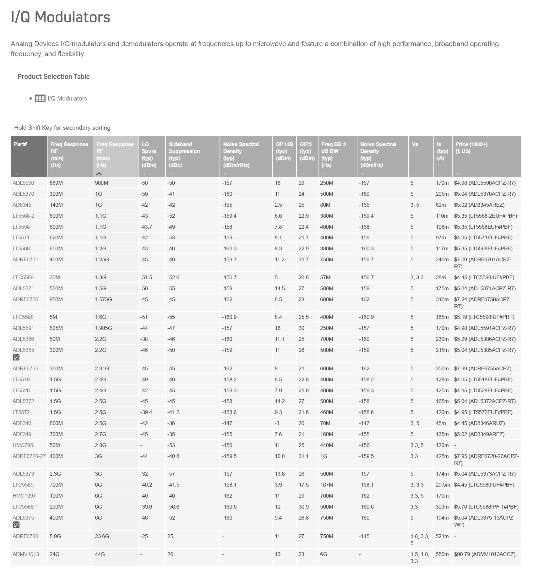
Tabelle von AD zu I/Q-Modulatoren davon 13 Typen für 2,4 GHz brauchbar
Das Portsdown-Projekt
Ein britisches Projekt, Sender für digitales Amateurfernsehen, nicht nur via QO-100, sondern auch terrestrisch. Es gibt zwei Versionen, "2018" war noch mit einem speziell entwickelten Sender aufgebaut, "2019" benutzt einen "Lime-SDR mini".
Die Sampleraten reichen von 88 kS/s bis 4 MS/s, dazu proportional steigt die nötige Sendeleistung, um QO-100 zu erreichen. Für das Maximum wird ein 100W-Sender mit einer 2,40m-Schüssel empfohlen.
Portsdown 2018
Portsdown 2019
Das DATV-Express-Projekt
ähnlich Portsdown aber ein Windows-PC statt Raspi
es unterstützt unterschiedliche Senderhardware:
- DATV-Express hardware Tx board
- LimeSDR-USB Tx/Rx board from Lime Micro
- LimeSDR-mini Tx/Rx board from Lime Micro
- PLUTO-ADALM Tx/Rx board from Analog Devices
Sendeendstufe
Es gibt noch wenige Endstufen für das 13cm-Band zu kaufen, hier ein paar Fundstellen:
Diskussion im AMSAT-Forum mit Auflistung
20 Watt-PA von Rene PE1CMO - Datenblatt zum verwendeten Doppeltransistor BLM2425M7S60P
20 Watt-PA von Hristiyan LZ5HP aus Sofia, Bulgarien laut DL7UKM auch ein Ampleon-Transistor BLP9G0722-20G
20 Watt-PA von Fred F6BVA, nur Bauvorschlag - Datenblatt zum verwendeten MW7IC2725
10W-PA von Michael Kuhne DB6NT und komplette Umsetzer mit 20W
13cm-PAs 0,9W von Ewald DK2DB (nur noch Abverkauf)
- die Transistoren FLU10 werden nicht mehr hergestellt
13cm-PAs von Dirk Fischer DK2FD
- und ein Schmalbandumsetzer für QO-100 für einen 2m oder 70cm-SSB-TX
Es gibt auch WLAN-Leistungsverstärker aus China, aber der Zoll beschlagnahmt sie oft, weil sie hier für WLAN nicht zulässig sind. Beim Bestellen daher verlangen, dass "Ham-Radio" oder ähnliches auf das Etikett geschrieben wird.
Zu älteren Bauanleitungen dürften die Transistoren nicht mehr lieferbar sein:
1986 in DUBUS mit BFQ34/BFQ68
1992 in DUBUS mit MGF-0904/0905
1994 in der CQ-DL mit CGY50/CLY5/CLY10
Der 1W-Typ CLY5 wurde zuletzt von Qorvo hergestellt, hier noch das Datenblatt und ein
Ersatztyp TQP7M9103 Aber der ist auch nur noch vereinzelt lieferbar, neuer Ersatztyp:
QPA9442 Mouser Einzelpreis 17,53 €
Ausgangstiefpass
Vor allem für Duo-Band-Antennen sollten Harmonische des Senders gut unterdrückt sein, da sie den Empfänger stören könnten.
Hier kommen vor allem koaxiale "tubular low pass filter" infrage.
Man kann sie kaufen, beispielsweise
oder selbst bauen. Dazu gibt es ein paar Anleitungen im Web.
- Bauanleitungen von F1FRV von 2002, Berechnungen mit Excel, Simulation mit RFSIM99, Fotos mehrerer Exemplare für die Bänder 2m - 13cm. Text in französischer Sprache, Übersetzungen der ersten Seiten in englisch und deutsch hier. Dazu gezippte Excel-Files
- Online-Rechner und eine Berechnung damit. Material soll ein Messingrohr mit etwa 6mm Innendurchmesser sein, z.B. Conrad-Nr . 221796 oder 293148, in das zwei SMA-Buchsen eingeschraubt werden. Die haben ein Außengewinde "1/4-36 UNS-2A" mit 6,35mm Durchmesser (1/4 inch) und 36 Gängen pro inch. Ein passender Gewindebohrer ist lieferbar, man könnte aber das Rohr auch mit einem Körnerschaft aufweiten und die Buchse einkleben.
QO-100 the first geostationary amateur radio transmitter
This article is primarily intended to provide a systematic overview of the topic; please refer to other articles or the forum for individual projects.
Due to favorable circumstances (a high-ranking politician of the state of Qatar is a radio amateur), a small amateur radio payload was also accommodated on the Es'Hail-2 TV satellite. The satellite, including the converter, was built in Japan by Mitsubishi and transported by SpaceX to its geostationary position, about three Earth diameters vertically above the equator, in November 2018. The amateur radio transceiver has been operational since February 2019. Wikipedia article on this
First entry via webradio
BATC-Webreceiver Cornwall IO70JB broad and narrowband
Dolianova Sardinia (JM49OJ)
Belgium (JO21FB)
Brasilia (GG56TV)
Southafrica (KG43AR)
Russia (KO92SO)
Russia (KO91OH)
Narrowband reception
Receiving antenna
A standard satellite dish is suitable for reception. A diameter of 60cm is sufficient, but 80-90cm offer more reserve. More exotic antenna shapes such as horn antennas are also conceivable. As usual, an LNB (low-noise block) is attached to the dish. More about the LNB below.
A larger diameter has little benefit for reception; the curve for the signal-to-noise ratio soon turns asymptotically horizontal.
The situation is different for the transmitter, where a larger diameter replaces a lack of transmission power. Offset dishes with a diameter of up to 2.40 m are still easy to obtain. Example: OP240L consisting of two half-shells measuring 1.20*2.40m. Transport is probably not cheap. Compared to 125cm, the gain is 6.3dB higher, corresponding to four times higher transmission power - with a smaller opening angle and higher requirements for mounting and alignment.
You can also use the same dish for transmitting; several "dual-band" antenna feeds are available, see below.
The lower transmission frequency also makes alignment easier and the opening angle is larger.
Aligning the antenna
You can have the antenna direction and rotation of the LNB (a few degrees different from vertical installation!) calculated for your own location here:
Satlex.de calculator for azimuth and elevation angles for 25.8° East
The required accuracy depends on the dish diameter. A cheap "satellite finder" doesn't help because the reception field strength is much lower than, for example, from Astra 19.2° East. An RTL-SDR can display the broadband beacon in the spectrum, allowing the antenna to be aligned to the maximum.
The TV channels transmitted by the satellite are listed here Lyngsat-Eshail-2. Unfortunately, their antenna lobe is aimed at North Africa, and in Europe there is probably not enough field strength to be able to target them.
You can use a compass to determine the horizontal direction, but this is influenced by metal parts in the surrounding area. More precise is a satellite image of the location from Google Earth, on which you look for clearly visible targets in the satellite direction, trees, chimneys or similar. For vertical alignment, a scale is often attached to the dish holder, but it is divided very roughly. In addition, the antenna holder must be exactly vertical, which is checked with a spirit level. You can also first align it with a known TV satellite and then try to rotate the dish by the difference angle. And finally, there are of course apps for smartphones.
Antenna polarization
Because of the different polarizations of QO-100 for the two signal directions, here are a few general comments: The choice of polarization has more practical reasons than physical ones. A vertically omnidirectional rod antenna is common for VHF/UHF mobile communications, while horizontally polarized long yagi antennas are common for wide area communications. On shortwave you choose between steep radiation or flat radiation, depending on the distance.
Polarization is particularly important for the Earth-Moon-Earth route, as physical phenomena lead to polarization rotations here, and a difference of just a few tenths of a dB can determine success or failure. As early as the mid-seventies, the "VHF communications" offered a switch box for Kreuzyagi antennas that, in addition to the four usual ones, also offered two linear 45 degree inclined positions. This meant you could quickly find out the currently most favorable polarization. Series of articles by Terry Bittan DJ0BQ VHF-Communications 3/1973 and 4/1973 and 1/1974, here is the circuit for 6 positions in Figure 8.
The space required by the antenna on the satellite may have played a role in the connection to QO-100. The circular polarization towards the satellite means that the location on Earth makes no difference. For the linear polarization of the route to earth, the LNB must be mounted at different angles depending on the location.
It is crucial that the polarization is chosen the same on both sides. No matter which one you choose, the following applies: This is optimal, one (“orthogonal” to it) has very high losses, depending on the propagation conditions. All other polarizations have a loss (close to the noise level) of up to 3 dB (half power).
A linearly polarized WiFi antenna is therefore not the optimal solution as a transmitting antenna; a circular antenna with the correct direction of rotation is the better solution, hence the following paragraph:
Dual-band antenna power
It is important that the receiver is not disturbed or even damaged by the transmission signal. The transmitter output should primarily suppress four and five times the frequency (9.6 / 12 GHz) with a low pass, as these fall within the reception range of the LNB. The beam lobe must approximately match. You also have to adhere to the different polarizations, for transmission always RHCP (right-hand circular polarized), which is reversed by the reflection on the dish, which means the feed antenna must be LHCP. For reception vertically for the narrowband range and horizontally for the broadband range. The latter can be switched in the LNB via the operating voltage, 18V=H 14V=V, (remember "higher voltage = "H"orizontal) If you don't have the 18V (only broadband reception), you can also rotate the LNB by 90 degrees , then both polarization levels are swapped.
Two horns one inside the other:
Dual feedhorn from OM6AA from Prague - manufacturer
The coaxial cables are each different by lambda/4 (for a 13cm wavelength times the shortening factor, this is about a 22-25 mm difference).
The power divider is a commercial one manufactured part by e-meca.com
two cable types were tested:
LMR195 (shortening factor 80%) and
SM141FEP (shortening factor 71%)
Horn emitter for 3cm and patch antenna for 13cm:
Building proposal from DJ7GP
- manufacturer
"POTY" (Patch Of The Year) G0MJW, PA3FYM, M0EYT
- Additions to this from HB9PZK
- Kit from PE1CKK
LNB (horn radiator) for 3cm and helix antenna for 13cm:
In the illustrations you can see the correct winding direction of the helix for QO-100 "LHCP".
A long helix antenna without a dish must be wound in the opposite direction.
The polarization cannot be switched. For this you have (like the patch antenna) a single feed without a power divider. A cross yagi or the Prague double horn mentioned above have two to four feed points, which are fed via power dividers and cable pieces of different lengths.
Building proposal Günter DF2GB
Building proposal by Rainer DM2CMB in TV-Amateur No. 194 p.5-8
There are more examples in the AMSAT forum.
LNB
Older LNBs with a dielectric resonator are not suitable for QO-100 due to excessive drift. Unfortunately, the manufacturers do not write this in the specifications. Therefore, there are some lists of PLL LNBs, but different hardware can also be offered under the same order number, there is no guarantee for this:
UHF Satcom PJM, southern GB
BATC Wiki
Pascal F4DAV
Frequency stability
Here too, the required accuracy at the high reception frequency is more critical than at the transmitter. This applies especially to the narrowband range. An SSB signal that constantly runs away is no fun. A drift of 100 Hz during a radio conversation is still tolerable. Based on 10 GHz, this is 0.01ppm (parts-per-million) or the eighth digit, which is not possible for standard crystal oscillators.
There are four options:
- Temperature compensated crystal oscillator (TCXO temperature compensated crystal oscillator),
- Heated crystal oscillator (OCXO oven controlled crystal oscillator)
- GPS-disciplined quartz oscillator (GPSDO GPS-disciplined oscillator)
- Rubidium frequency standard
For reception, there is still the option of constantly readjusting the receiver by checking the beacon, solutions available so far:
- Windows software SDR Console by Simon G4ELI
The idea for drift compensation comes from Moe Wheatley AE4JY back then for the AO-40.
Before downloading, Simon asks for a donation for dog food now or tomorrow or sometime...
- Raspi software Satcontrol by Frank DL3DCW with GQRX and two RTL-SDR sticks
However, the drift between the two RTL-SDR cannot be corrected in this way.
Reception with RTL-SDR
The cheapest receivers are USB sticks for DVB-T or DAB in conjunction with a PC or the Raspberry Pi.
A "luxury version" from rtl-sdr.com with TCXO and shielding metal housing
There are also cheaper Chinese replicas, but the shielding was sloppy and the housing is not well contacted.
The RTL-SDR also has the advantage that you can choose the reception frequency over a wide range. You don't need a reception converter from the LNB to an amateur band to use an SSB transceiver.
There are some receiver programs for Windows:
- SDR-Console- as written above, particularly recommended because of the drift compensation
and many more, a link list on rtl-sdr.com mentions the following:
- SDR# (or SDR sharp)
- HDSDR
- SDR-RADIO.COM
- Linrad (Windows/Linux/Mac)
- CubicSDR (Windows/Linux/Mac)
- SDRUno
- OpenWebRX (Python Based)
- cuSDR
- PowerSDR
- QtRadio (Windows/Linux)
- Multimode (GNU Radio)
- QuestaSDR
- QIRX SDR
- SeeDeR
Software for Linux, Mac, Raspi, Android:
- GQ-RX - Tutorial on this is based on GNU Radio
- WebRadio (Linux)
- Sdrangelove (Linux)
- Natpos (Linux)
- ShinySDR (web interface, runs on Mac, Linux, Raspi...)
- RF Analyzer (Android)
- Kukuruku (Browser Based)
Also listed: some paid programs with free trial versions and special programs.
Still missing from the list is SDRangel for Windows and Linux:
"SDR Rx/Tx software for Airspy, Airspy HF+, BladeRF, HackRF, LimeSDR, PlutoSDR, RTL-SDR, SDRplay RSP1 and FunCube"
Echo cancellation
just an idea...
The pure transit time of the signal over 2*38,000 km causes a delay of around a quarter of a second. In addition, there are delays, especially due to digital filters, with web radio its computing time and the running time through the web.
A so-called echo compensation has long been used for telephone signals to suppress disturbing echoes. For the QO-100, you could try something similar, subtracting the microphone signal from the received signal with a delay of the propagation time in the correct amplitude and phase. You could hear hecklers loudly, while your own broadcasts, which are more annoying, would be quieter. However, since the SSB signal would have to be set exactly to zero beat, only a DSP could use the delayed signal as a pattern function using an "adaptive filter". Simple solutions using analogue technology are beyond capacity here.
Narrowband transmitter
In the narrowband range, all common amateur radio operating modes up to 2700 Hz bandwidth are permitted, i.e. SSB, CW and digital modes. Bandplan here divided into CW / narrow Digimodes up to 500Hz / Digimodes / mixed modes / SSB only. FM is therefore not permitted because it is too wide. There are several options for generating these modulations in the 13cm band:
- classic SSB radio and transverter
- Preparation of the analog or digital modulation to the I/Q signal and up-conversion with an I/Q modulator
or special hardware like
- Lime-SDR 100 kHz to 3.8 GHz
- Red Pitaya 125 MS/s, (additional transverter required)
- Adalm-Pluto 325 MHz to 3.8 GHz
- HackRF one 1 MHz to 6 GHz
- BladeRF 47 MHz to 6 GHz
etc. which already contain high frequency generation
There are three classic methods for generating SSB:
- Filter method (one mixer)
- Phase method (two mixers, also included in an I/Q modulator IC, for example)
- "third method" according to Weaver (four mixers)
A high starting frequency is more advantageous for implementation because the filters for suppressing the oscillator and image frequencies are less critical. So 70cm rather than 2m or shortwave.
Suppliers of finished transverters are listed again below in the list of 13cm transmitters:
There are also some building suggestions or kits.
Holger Eckardt DF2FQ published an interesting converter in “Funkamateur” 9/2019. By using the phase method for implementation, it achieves good LO and image frequency suppression on a tiny board, even from the 2m (or 10m) band. A photo of the circuit board (middle of the first page) is shown in the table of contents of the booklet [1].
The circuit consists of a typical I/Q modulator IC ADRF6703 with two mixers, LO phase shifter and PLL -VCO. Driven with a PIC12F629 and 26 MHz TCXO. Can be tuned in 1 MHz steps via serial interface. At the input the second phase shifter, depending on the configuration for a 2m or 10m SSB signal, a double-T LC filter. The only filtering measure at the output is a Murata SAW filter SF2173E. Interference suppression for 2m 60 dB, for 10m still 47 dB. Output power 50mW at 38 dB two-tone IM distance. If demand is high, he wants to produce assembled circuit boards.
"Image transfer" with Picfall
Roland, PY4ZBZ/F5NCB from Brazil has programmed an unusual option for call sign transmission, also via QO-100, the Picfall program. Here is his website. and on QSL.net Texts about satellite radio
Unfortunately there is only a description in Portuguese. He can transmit via QO-100, Brazil is partially within the footprint area.
In this tutorial you can download the Windows software.
Broadband reception (digital TV)
MiniTiouner
A dedicated receiver just for amateur TV with a NIM satellite tuner Serit FTS-4334L BATC wiki page about this , the reception data of which is displayed via USB connection in the PC under Windows. No other receiver offers many measurement options in addition to normal reception and an adjustable sample rate down to 88 kS/s.
The Minitiouner does not yet provide for 14/18V switching for the polarization of the LNB, and does not contain any digital switching according to DiSEqC protocol, as normal satellite tuners offer.
For tax reasons, partial kits are only sold to BATC members; "cyber membership" with e-mail access to the club magazine costs 8 pounds annually (see below).
The French amateur radio club REF also offers two parts, but are currently sold out:
- Minitiouner Pro incl. Tuner ("Pro"=2 reception channels via separate USB ports, 18V DC/ DC converter and DiSEqC feed with RT5047 to the LNB, optional I2C display connection, all included in extended MiniTioune software) 109, 50 € - Documentation (in French)
- Serit NIM tuner FTS-4334L individually €35.00
UK BATC Wiki
Windows software MiniTioune - registration required, currently not being further developed
Some screenshots of the MiniTioune software at 88kS/s.
current alternative software Open Tuner without registration
the site of the South African Open Tuner author Tom ZR6TG
Download from Github
Due to lower bandwidth, the effort required for transmission power and dish size decreases significantly. As you can see, a good resolution can still be achieved. Maximum bandwidth (4 MHz) and the 125 kHz (factor 32) used here theoretically make a 15 dB difference in the requirements. Instead of 100 W and 2.4 m, for example, 10 W (-10 dB) and around 1.2 m (-6 dB) could be sufficient.
RTL-SDR with SDRangel
You can also watch the broadband TV signal with an RTL-SDR: Instructions for DATV reception with SDRangel
TV satellite receiver
Most satellite receivers cannot handle the low bit rates of QO-100, but there are exceptions.
The reception range of most satellite receivers starts too high for direct reception to set QO-100. Here you can trick some types, e.g. by entering a wrong LO frequency.
OCTAGON SF8008 instructions for QO-100 reception
Another solution to the frequency problem is a reception converter, here for the simultaneous conversion of the broadband range to 1340 MHz and the narrowband range 144MHz.
Broadband transmitter
Raspberry Pi as a digital video modulator
There is software RPI-DATV for the Raspberry Pi, which directly supplies the (digital) I/Q baseband signal for DVB-S from two GPIO outputs. Bitrate-dependent low-pass filtering in front of the modulator is therefore necessary. The input is either a Raspi camera or a video digitizer on the USB port. For test purposes there is even a direct output of a complete broadcast signal in the 70cm band, the so-called "ugly" mode. You just have to connect a piece of wire to a GPIO pin as a transmitting antenna and you can receive the signal with the Minitiouner, for example. Operation via touchscreen on the Raspi. A pre-programmed SD card can be purchased in the BATC shop can be purchased. For tax reasons you have to become a member of the BATC. One year from Germany costs 8 or 30 pounds (CQ-TV magazine subscription via e-mail/print).
The software on Github
Wiki of the BATC
I/Q modulator
In order to convert an I/Q baseband signal to 2.4 GHz (or to generate SSB there directly using the phase method), complete I/Q modulator ICs have been available for around 20 years, primarily from Analog Devices.
A circuit with AD8346 from 2002 , Chapter 6
Table from AD to I/Q modulators of which 13 types are usable for 2.4 GHz
The Portsdown Project
A British project, transmitter for digital amateur television, not only via QO-100 but also terrestrial. There are two versions, "2018" was built with a specially developed transmitter, "2019" uses a "Lime-SDR mini".
The sample rates range from 88 kS/s to 4 MS/s, and the transmission power required to achieve QO-100 increases proportionally. For the maximum, a 100W transmitter with a 2.40m dish is recommended.
Portsdown 2018
Portsdown 2019
The DATV Express Project
similar to Portsdown but a Windows PC instead of Raspi
it supports different transmitter hardware:
- DATV Express hardware Tx board
- LimeSDR-USB Tx/Rx board from Lime Micro
- LimeSDR-mini Tx/Rx board from Lime Micro
- PLUTO-ADALM Tx/Rx board from Analog Devices
Transmit output stage
There are still a few power amplifiers available for the 13cm band, here are a few places to find them:
Discussion in the AMSAT forum with a list
20 Watt PA by Rene PE1CMO .html - data sheet for the double transistor used BLM2425M7S60P
20 watt PA by Hristiyan LZ5HP from Sofia, Bulgaria -sg-laboratory-ltd-power-amplifier-for-2-4ghz-up-link/ according to DL7UKM also an Ampleon transistor ghz-transistors/BLP9G0722-20G.html BLP9G0722-20G
20 watt PA by Fred F6BVA, construction proposal only en/data-sheet/MW7IC2725N.pdf - Data sheet for the MW7IC2725 used
10W-PA by Michael Kuhne DB6NT and complete converters with 20W
13cm-PAs 0.9W from Ewald DK2DB (only for sale)
- the FLU10 transistors are no longer manufactured
13cm PAs from Dirk Fischer DK2FD
- and a narrowband converter for QO-100 for a 2m or 70cm SSB-TX
There are also WiFi power amplifiers from China, but customs often confiscates them because they are not allowed for WiFi here. When ordering, ask that “Ham-Radio” or something similar be written on the label.
The transistors may no longer be available for older building instructions:
1986 in DUBUS with BFQ34/BFQ68
1992 in DUBUS with MGF-0904/0905
1994 in the CQ-DL with CGY50/CLY5/CLY10
The 1W type CLY5 was last manufactured by Qorvo, here is the data sheet and a
Replacement type TQP7M9103 But it is rarely available, new replacement type:
QPA9442 Mouser unit price €17.53
Output low pass
Especially for duo-band antennas, harmonics from the transmitter should be well suppressed as they could interfere with the receiver.
Coaxial “tubular low pass filters” are particularly suitable here.
You can buy them, for example
or build it yourself. There are a few instructions on the web for this.
- F1FRV construction instructions from 2002, calculations with Excel, simulation with -software/ RFSIM99, photos of several copies for the bands 2m - 13cm. Text in French, translations of the first pages in English and German here. Zipped Excel files
- online calculator and a calculation with it. The material should be a brass tube with an inner diameter of around 6mm, e.g. Conrad no. 221796 or 293148, into which two SMA -sockets are screwed in. They have an external thread "1/4-36 UNS-2A" with a diameter of 6.35mm (1/4 inch) and 36 threads per inch. A suitable tap is available, but you could also expand the tube with a punch shaft and glue the bushing in.
Links
QO-100 im Forum
Es'hail2 - erster geosationärer Amateurfunk-Satellit
QO-100 und Schmalband-Digimodes
Präziser HF- Generator mit ADF4351... (speziell für QO-100)
zu Picfall
ebenfalls Picfall