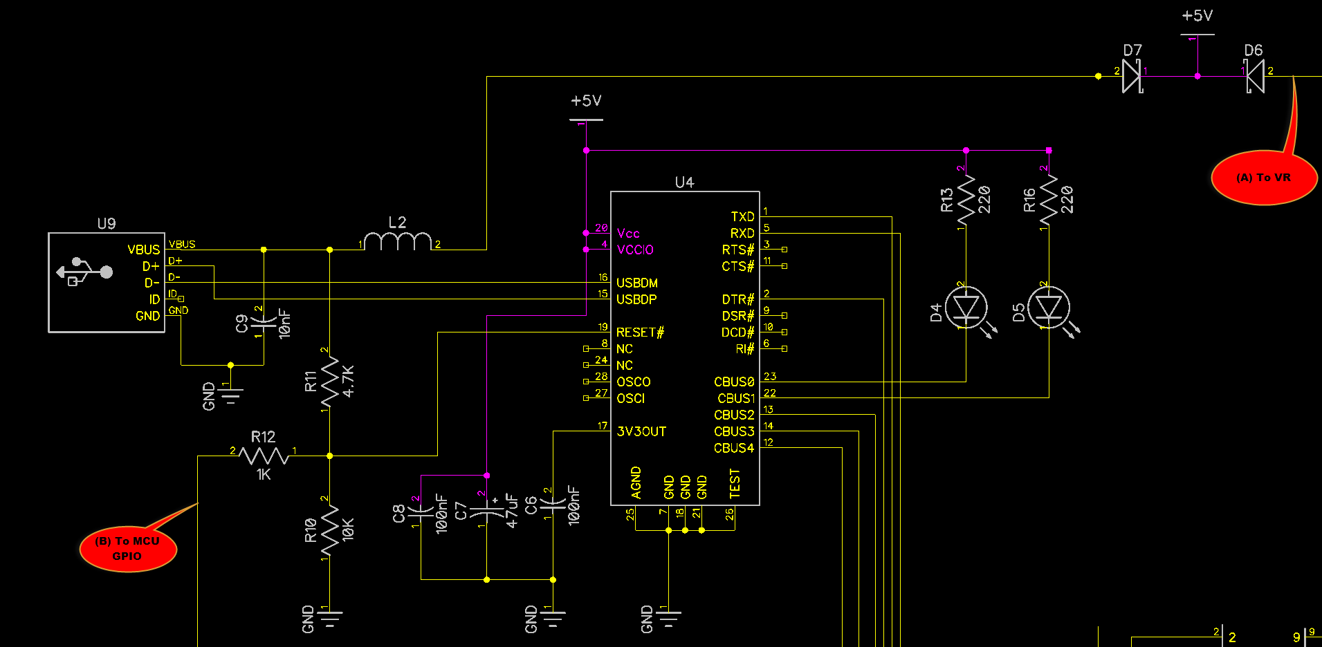
First of all I am sorry to write in English. If this is inappropriate,
feel free to delete my post.

What I am trying to achieve is detect from MCU, whenever FTDI(FT232R)
chip is connected to USB(not enumerated, just powered up from USB).

I came up with the circuit attached.

By device usage restrictions, only 1 power supply can be connected -
either USB or external. We are not considering if user connects both at
the same time, it's out of scope. What I expect from the circuit:

- When USB is connected, then MCU and FTDI will be powered on and on pin
(B) of MCU I can detect logical 1 and know that USB is connected.

- When External power is connected, then there will be logical 0 on pin
(B) and I can detect that there is no USB connection.

The question is - would it work the way I described or I missed
something? Should I avoid R10/R11 due to additional current draw and
directly connect VBUS to (B)? I am very new to hardware design and I
feel like this forum is very powerful in knowledge.
Angehängte Dateien:
-

ftdi2.png
42 KB
As far as i see it, you might expect roughly 2/3rds of 5 Volts (about
3.4 Volts) on your Signal (B) when USB is plugged into a powered USB
Port. I'm not sure though if the Signal is valid to be wired to the
Reset Pin of the FTDI chip. If in doubt, check with the datasheet.

Souren A. schrieb:
> Should I avoid R10/R11 due to additional current draw and
> directly connect VBUS to (B)?

As long as your MC is satisfied with a 3.3 to 3.4 Volts high signal and
will draw less than a few 100 uA from it it should work. The current
drawn by R10/R11 is neglectible when compared with the rest of the
circuit, as its only about 5/15000 ~ 330 uA.
Angehängte Dateien:
-

ftdi3.png
110 KB
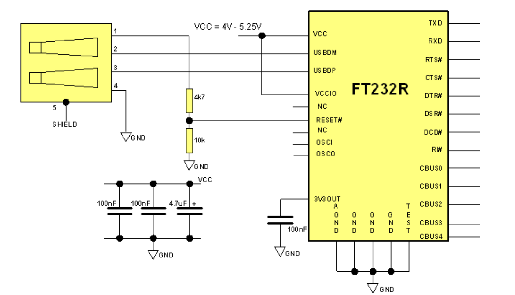
Thanks for reply. In fact I took the reference design from FT232R
datasheet as well as resistor values - attached. Also the datasheet of
MCU(ATMega328) describes logical high voltage min 0.6*VCC and max VCC+
0.5. For 5V VCC it should be from 3 to 5.5V. So the circuit should
detect USB connection perfectly, right?
Souren A. schrieb:
> So the circuit should
> detect USB connection perfectly, right?

Yes, that looks good. Only keep in mind to not draw too much current for
the MC detection pin. If its simply the input to a microcontroller,
everything does work.
Matthias Sch. schrieb:
> Souren A. schrieb:
>> So the circuit should
>> detect USB connection perfectly, right?
>
> Yes, that looks good. Only keep in mind to not draw too much current for
> the MC detection pin. If its simply the input to a microcontroller,
> everything does work.

Yes, it's connected to GPIO pin directly.
Thank you so much!
Bitte melde dich an um einen Beitrag zu schreiben. Anmeldung ist kostenlos und dauert nur eine Minute.
Bestehender Account
Schon ein Account bei Google/GoogleMail? Keine Anmeldung erforderlich!
Mit Google-Account einloggen
Mit Google-Account einloggen
Noch kein Account? Hier anmelden.