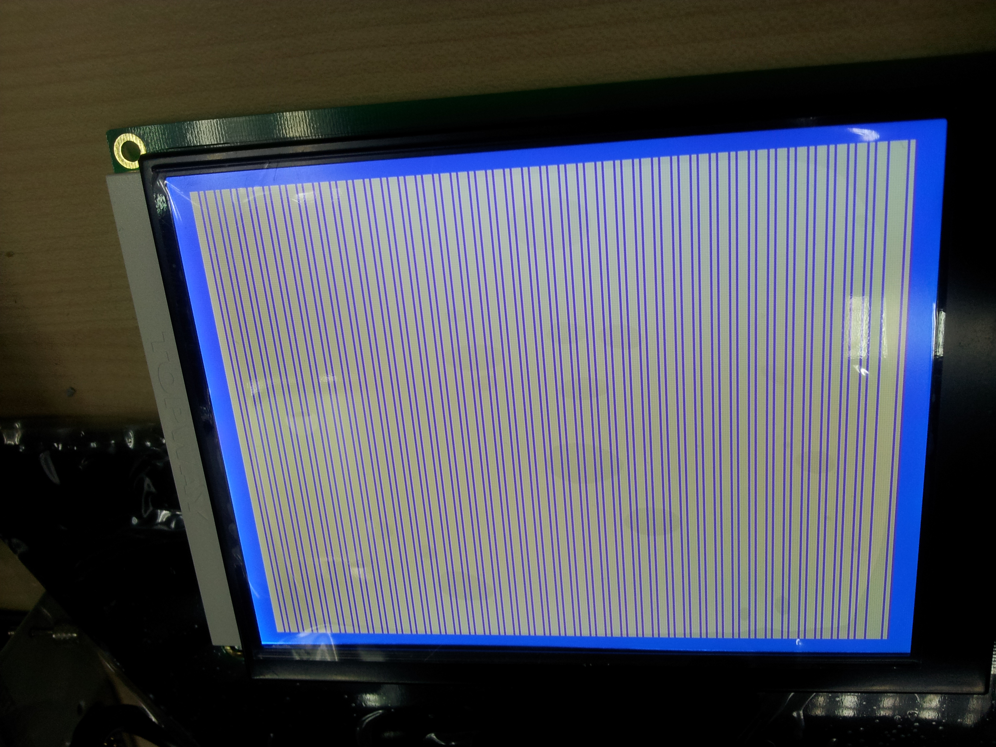
Attached with my coding and the picture i had initial(not success all
the time).

This screen only show up on certain number of try.

I start my program and kill it, and start again, until this screen
showed.

I am using parallel pin with parapin library.

anyone can help on this ?

* after initial, i kill my program without RST again and run a 0x58 and
0x59 loop (command), it work.
* after reset crystal is in high states, after 0x40, crystal was
measured, it osilate in 10MHz

I am using TOPWAY LM2088E

timing diagram clk is the /WR

i had tight my RD to the VDD
Angehängte Dateien:
-

IMG_20130719_143132.jpg
3,1 MB -

Capture.PNG
36 KB
Wong J. schrieb:
> anyone can help on this ?

Hello Wong,

I'd suggest you try your code step by step and measure the output at the
LCD every step - try to learn to debug the problems yourself. Then you
can find out if there is anything wrong and what.

And it would be a good idea to check whether the timings are correct,
whether there are additional prerequisites and initializations.

And third I'd suggest you improve your english and try to explain your
problem a bit deeper and in a more logical context.

rgds
ok, i will try to explain again on my progress, i had debug more than
two weeks time, so hope there is some added information to driving this
LCD.

just for information, I only able to use screen on and screen off after
a random success initialization process.

I had no clue due to the command for 0x58 and 0x59 just work well, 0x40
and a delay can make the crystal start oscillate. But the initialization
process not really working, and no even a cursor in text mode and only
show the screen i attached on the last post.

*bad english, I had tried my best to explain my situation. Thanks for
reviewing.
Angehängte Dateien:
-

uc.PNG
67 KB
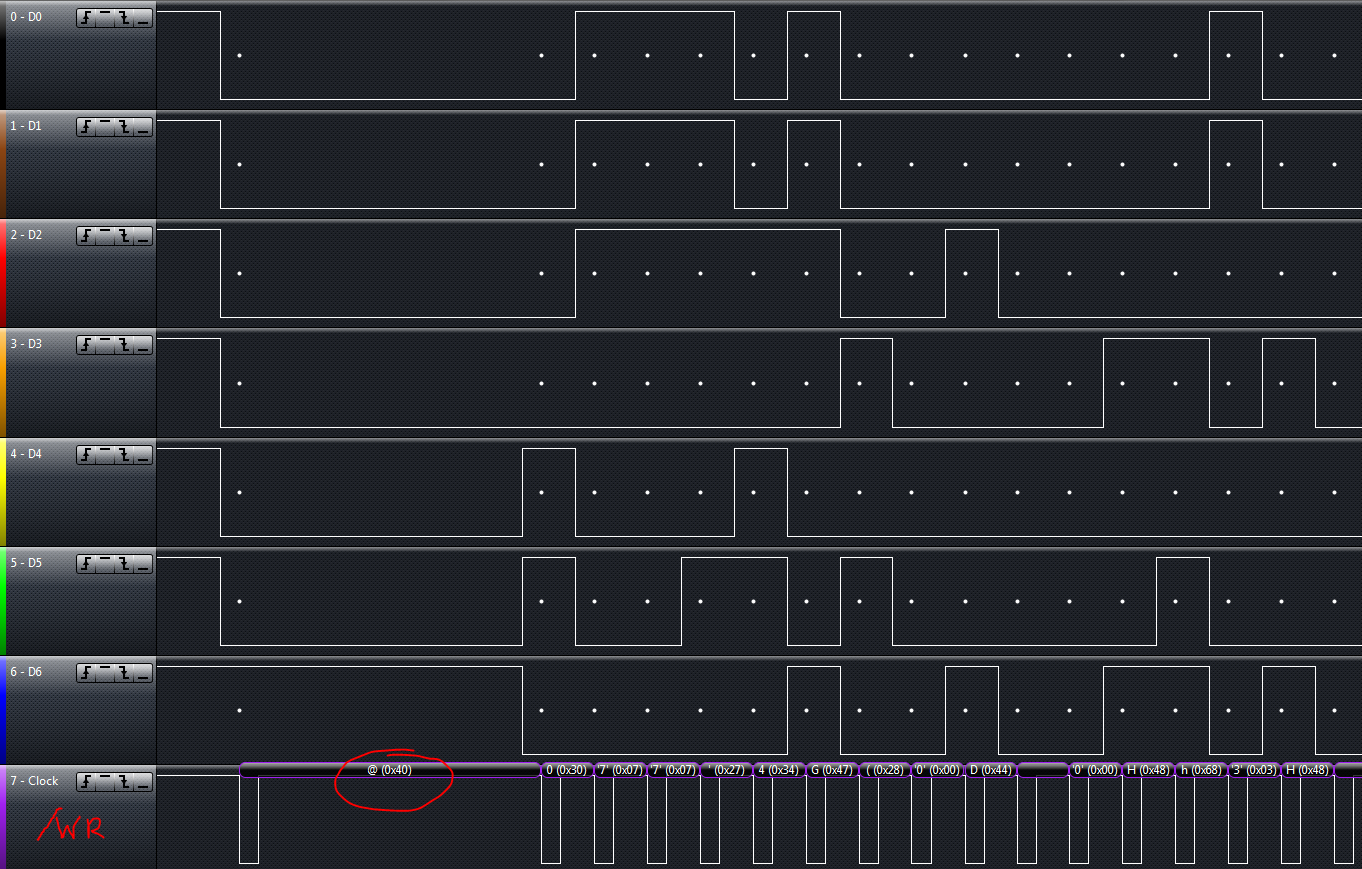
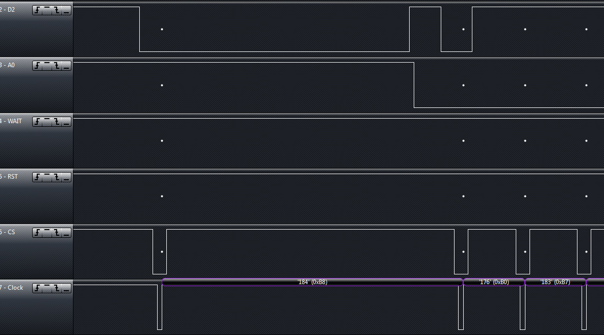
I had try everything i can done, Now I am using 18F4520 now to generate
more sharp output.

Same to parallel port, only able to make the oscillator to work after
reset follow with a 0x40 command.

note 1: WR toggle inside the CS toggle.

WAIT pin produce a pulse on each WR fallig edge.

any idea on this ?

I really hope someone can give me a set of working initialization signal
capture so I can generate the same pattern of wave to light up my LCD.
At least using the same timing as possible.
Problem solve:

The supply for GLCD and signaling output must be the same. Common ground
and voltage.

Different controller with different command sequence

18F4520:

/CS - /WR - CS - WR

PARAPIN:

/CS - /WR - WR - CS

Conclusion:

Check the WAIT pin to determine the pattern of sending is  a valid
communication or not.

WAIT signal is triggered when the WR pin low. A small pulse is detected.
Bitte melde dich an um einen Beitrag zu schreiben. Anmeldung ist kostenlos und dauert nur eine Minute.
Bestehender Account
Schon ein Account bei Google/GoogleMail? Keine Anmeldung erforderlich!
Mit Google-Account einloggen
Mit Google-Account einloggen
Noch kein Account? Hier anmelden.