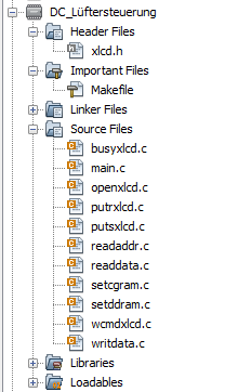
Hallo,

ich habe i wie Probleme mit der von Microchip bereitgestellten Lib das
LCD in Gang zu setzen. Ich hoffe ihr könnt mir helfen.

Im Anhang findet ihr ein Screenshot der eingebundenen Files.

Das LCD läuft im 4-Bit modus liegt mi seinen Datenpins 4-7 an PORTD 0-3,
RS liegt an E0 RW an E1 und Enable an E2.

hier mal das xlcd.h File
1 | #ifndef __XLCD_H
|
2 | #define __XLCD_H
|
3 | #include "p18cxxx.h" |
4 | /* PIC18 XLCD peripheral routines.
|
5 | *
|
6 | * Notes:
|
7 | * - These libraries routines are written to support the
|
8 | * Hitachi HD44780 LCD controller.
|
9 | * - The user must define the following items:
|
10 | * - The LCD interface type (4- or 8-bits)
|
11 | * - If 4-bit mode
|
12 | * - whether using the upper or lower nibble
|
13 | * - The data port
|
14 | * - The tris register for data port
|
15 | * - The control signal ports and pins
|
16 | * - The control signal port tris and pins
|
17 | * - The user must provide three delay routines:
|
18 | * - DelayFor18TCY() provides a 18 Tcy delay
|
19 | * - DelayPORXLCD() provides at least 15ms delay
|
20 | * - DelayXLCD() provides at least 5ms delay
|
21 | */
|
22 | |
23 | /* Interface type 8-bit or 4-bit
|
24 | * For 8-bit operation uncomment the #define BIT8
|
25 | */
|
26 | /* #define BIT8 */
|
27 | |
28 | /* When in 4-bit interface define if the data is in the upper
|
29 | * or lower nibble. For lower nibble, comment the #define UPPER
|
30 | */
|
31 | /* #define UPPER */
|
32 | |
33 | /* DATA_PORT defines the port to which the LCD data lines are connected */
|
34 | #define DATA_PORT PORTD
|
35 | #define TRIS_DATA_PORT TRISD
|
36 | |
37 | /* CTRL_PORT defines the port where the control lines are connected.
|
38 | * These are just samples, change to match your application.
|
39 | */
|
40 | #define RW_PIN LATEbits.LATE1 /* PORT for RW */ |
41 | #define TRIS_RW TRISEbits.TRISE1 /* TRIS for RW */ |
42 | |
43 | #define RS_PIN LATEbits.LATE0 /* PORT for RS */ |
44 | #define TRIS_RS TRISEbits.TRISE0 /* TRIS for RS */ |
45 | |
46 | #define E_PIN LATEbits.LATE2 /* PORT for D */ |
47 | #define TRIS_E TRISEbits.TRISE2 /* TRIS for E */ |
48 | |
49 | /* Display ON/OFF Control defines */
|
50 | #define DON 0b00001111 /* Display on */ |
51 | #define DOFF 0b00001011 /* Display off */ |
52 | #define CURSOR_ON 0b00001111 /* Cursor on */ |
53 | #define CURSOR_OFF 0b00001101 /* Cursor off */ |
54 | #define BLINK_ON 0b00001111 /* Cursor Blink */ |
55 | #define BLINK_OFF 0b00001110 /* Cursor No Blink */ |
56 | |
57 | /* Cursor or Display Shift defines */
|
58 | #define SHIFT_CUR_LEFT 0b00000100 /* Cursor shifts to the left */ |
59 | #define SHIFT_CUR_RIGHT 0b00000101 /* Cursor shifts to the right */ |
60 | #define SHIFT_DISP_LEFT 0b00000110 /* Display shifts to the left */ |
61 | #define SHIFT_DISP_RIGHT 0b00000111 /* Display shifts to the right */ |
62 | |
63 | /* Function Set defines */
|
64 | #define FOUR_BIT 0b00101100 /* 4-bit Interface */ |
65 | #define EIGHT_BIT 0b00111100 /* 8-bit Interface */ |
66 | #define LINE_5X7 0b00110000 /* 5x7 characters, single line */ |
67 | #define LINE_5X10 0b00110100 /* 5x10 characters */ |
68 | #define LINES_5X7 0b00111000 /* 5x7 characters, multiple line */ |
69 | |
70 | #ifdef _OMNI_CODE_
|
71 | #define PARAM_SCLASS
|
72 | #else
|
73 | #define PARAM_SCLASS auto
|
74 | #endif
|
75 | |
76 | #ifndef MEM_MODEL
|
77 | #ifdef _OMNI_CODE_
|
78 | #define MEM_MODEL
|
79 | #else
|
80 | #define MEM_MODEL far /* Change this to near for small memory model */ |
81 | #endif
|
82 | #endif
|
83 | |
84 | /* OpenXLCD
|
85 | * Configures I/O pins for external LCD
|
86 | */
|
87 | void OpenXLCD(PARAM_SCLASS unsigned char); |
88 | |
89 | /* SetCGRamAddr
|
90 | * Sets the character generator address
|
91 | */
|
92 | void SetCGRamAddr(PARAM_SCLASS unsigned char); |
93 | |
94 | /* SetDDRamAddr
|
95 | * Sets the display data address
|
96 | */
|
97 | void SetDDRamAddr(PARAM_SCLASS unsigned char); |
98 | |
99 | /* BusyXLCD
|
100 | * Returns the busy status of the LCD
|
101 | */
|
102 | unsigned char BusyXLCD(void); |
103 | |
104 | /* ReadAddrXLCD
|
105 | * Reads the current address
|
106 | */
|
107 | unsigned char ReadAddrXLCD(void); |
108 | |
109 | /* ReadDataXLCD
|
110 | * Reads a byte of data
|
111 | */
|
112 | char ReadDataXLCD(void); |
113 | |
114 | /* WriteCmdXLCD
|
115 | * Writes a command to the LCD
|
116 | */
|
117 | void WriteCmdXLCD(PARAM_SCLASS unsigned char); |
118 | |
119 | /* WriteDataXLCD
|
120 | * Writes a data byte to the LCD
|
121 | */
|
122 | void WriteDataXLCD(PARAM_SCLASS char); |
123 | |
124 | /* putcXLCD
|
125 | * A putc is a write
|
126 | */
|
127 | #define putcXLCD WriteDataXLCD
|
128 | |
129 | /* putsXLCD
|
130 | * Writes a string of characters to the LCD
|
131 | */
|
132 | void putsXLCD(PARAM_SCLASS char *); |
133 | |
134 | /* putrsXLCD
|
135 | * Writes a string of characters in ROM to the LCD
|
136 | */
|
137 | void putrsXLCD(const char *); |
138 | |
139 | /* User defines these routines according to the oscillator frequency */
|
140 | extern void DelayFor18TCY(void); |
141 | extern void DelayPORXLCD(void); |
142 | extern void DelayXLCD(void); |
143 | |
144 | #endif
|
Und jetzt noch das main.c
1 | /*
|
2 | * File: main.c
|
3 | * Author: Daniel
|
4 | *
|
5 | * Created on 24. September 2013, 16:46
|
6 | */
|
7 | |
8 | //-------
|
9 | //Includes
|
10 | //-------
|
11 | |
12 | #include <stdio.h> |
13 | #include <stdlib.h> |
14 | #include <xc.h> |
15 | #include <string.h> |
16 | #include "xlcd.h" |
17 | |
18 | |
19 | |
20 | |
21 | //------
|
22 | //Configs
|
23 | //-----
|
24 | |
25 | #pragma config OSC = INTIO7 //internal HS OSC
|
26 | #pragma config PWRT = ON //Powerup Timer
|
27 | #pragma config PBADEN = OFF
|
28 | #pragma config WDT = OFF //Watchdog Timer
|
29 | #pragma config LVP = OFF //Low Voltage ICSP
|
30 | |
31 | //------_
|
32 | //Defines
|
33 | //-------
|
34 | |
35 | #define _XTAL_FREQ 32000000 //32MHz CPU
|
36 | #define Timer0 INTCONbits.TMR0IF //Timer0 Interrupt
|
37 | #define Timer0IE INTCONbits.TMR0IE //Timer0 Interrupt Enable Bit
|
38 | |
39 | |
40 | |
41 | |
42 | //--------
|
43 | //Prototypes
|
44 | //--------
|
45 | |
46 | void init(void); |
47 | void ADC_init(); |
48 | void interrupt ISR(); |
49 | unsigned long time(); |
50 | void pwm_init(); |
51 | void pwm_on(); |
52 | void pwm_off(); |
53 | int getspeed(); |
54 | void DelayFor18TCY(void); |
55 | void DelayPORXLCD(void); |
56 | void DelayXLCD(void); |
57 | |
58 | //--------
|
59 | //Globale
|
60 | //--------
|
61 | |
62 | unsigned long time_ms=0; |
63 | int setspeed=0; |
64 | |
65 | //-----
|
66 | //Main
|
67 | //-----
|
68 | |
69 | int main(void) |
70 | {
|
71 | init(); |
72 | ADC_init(); |
73 | pwm_init(); |
74 | OpenXLCD( FOUR_BIT & LINES_5X7 ); // 8-Bit Modus, 5x7 Zeichen, mehrzeilig |
75 | while(BusyXLCD()); |
76 | unsigned short i; |
77 | while(1) |
78 | {
|
79 | pwm_on(); |
80 | |
81 | CCPR1L=getspeed(); |
82 | |
83 | }
|
84 | |
85 | }
|
86 | |
87 | |
88 | |
89 | void init(void) |
90 | {
|
91 | LATA=0; |
92 | LATB=0; |
93 | LATC=0; |
94 | OSCCON = 0b01111100; // 8 MHz, primary Oscillator |
95 | OSCTUNE =0b01000000; // PLL aktiviert, Takt 32 MHz |
96 | INTCONbits.GIE=1; // Gloab Interrups enable |
97 | TRISA=0b00011111; //Port A 0-4 als Input rest Output |
98 | TRISEbits.RE0=1; |
99 | TRISB=0; //Port B alle Outputs |
100 | TRISC=0; //Port C alle Outputs |
101 | TRISD=0; // Port D alles Ausgänge |
102 | TRISE=0; // Port E alles Ausgänge |
103 | T0CON=0b11000010; //TMR0On, 8bit, Internal Clock sorce,1:8 Prescaler |
104 | TMR0L=5; |
105 | INTCONbits.T0IE=1; // Enable Interrupt |
106 | INTCON2bits.TMR0IP=1; //HIGH PRIORITY Interrupt |
107 | |
108 | }
|
109 | |
110 | |
111 | void interrupt ISR() |
112 | {
|
113 | if (Timer0&&Timer0IE) |
114 | {
|
115 | time_ms++; |
116 | TMR0L=5; |
117 | Timer0=0; |
118 | |
119 | }
|
120 | |
121 | }
|
122 | |
123 | void ADC_init() |
124 | {
|
125 | VCFG0=0; // Vref=5V |
126 | VCFG1=0; // Vref=0V |
127 | ADFM=0; // Linksbündig BIT 9-2 in ADRESH rest in ADRESL |
128 | PCFG0=0; // AN0-AN2 als analog Port |
129 | PCFG1=0; //AN0-AN2 als analog Port |
130 | PCFG2=1; //AN0-AN2 als analog Port |
131 | PCFG3=1; //AN0-AN2 als analog Port |
132 | ADCON2bits.ACQT0=1; // A/D Acquisition Time = 12Tad |
133 | ADCON2bits.ACQT1=0; |
134 | ADCON2bits.ACQT2=1; |
135 | ADCON2bits.ADCS0=0; // A/D Conversion Clock = Fosc/32 |
136 | ADCON2bits.ADCS1=1; |
137 | ADCON2bits.ADCS2=0; |
138 | ADON=1; //ADC Modul einschalten |
139 | |
140 | }
|
141 | |
142 | |
143 | void pwm_init() |
144 | {
|
145 | TRISCbits.RC2=1; |
146 | PR2=255; //Periode=(PR2+1)*4*T_OSC*TMR2PS - bei PR2=249 und TMR2PS=1:16 ergibt sich 2kHz |
147 | CCP1CON=0b00001100; //PWM Mode, Single Output P1A |
148 | CCPR1L=0; //Duty=0 |
149 | PIR1=0; //Clear TMR2 Interruptflag |
150 | T2CONbits.T2CKPS=0b10; //Prescaler=16 |
151 | TMR2ON=1; |
152 | |
153 | }
|
154 | |
155 | void pwm_on() |
156 | {
|
157 | CCP1CONbits.CCP1M=0b1100; //PWM Mode active |
158 | while(TMR2IF==0); |
159 | TRISCbits.RC2=0; // Port P1A |
160 | ECCPASE=0; |
161 | }
|
162 | |
163 | void pwm_off() |
164 | |
165 | {
|
166 | CCP1CONbits.CCP1M=0b0000; //PWM Mode OFF |
167 | ECCPASE=1; |
168 | }
|
169 | |
170 | int getspeed() |
171 | {
|
172 | ADCON0bits.CHS0=0; //ACD auf AN0 ausrichten |
173 | ADCON0bits.CHS1=0; //ACD auf AN0 ausrichten |
174 | ADCON0bits.CHS2=0; //ACD auf AN0 ausrichten |
175 | ADCON0bits.CHS3=0; //ACD auf AN0 ausrichten |
176 | ADCON0bits.GO=1; |
177 | while(ADCON0bits.GO); |
178 | return (ADRESH); |
179 | }
|
180 | |
181 | void DelayFor18TCY(void) |
182 | {
|
183 | _delay(18); |
184 | }
|
185 | |
186 | |
187 | void DelayPORXLCD(void) |
188 | {
|
189 | __delay_ms(15); |
190 | }
|
191 | |
192 | |
193 | void DelayXLCD(void) |
194 | {
|
195 | __delay_ms(5); |
196 | }
|
Mein Problem ist, dass sobald ich die OpenXLCD Funktion aufrufe quasi
nichts mehr geht. Vllt kann jemand von euch Profis mal drübergucken und
findet den Fehler gleich.

Bin leider (noch) nich so der Profi was die Mikrocontrollerei betrifft
:(