
Hallo,

Ich bin gerade dabei mich beim STM32F407 MC einzuarbeiten und möchte für
Debug Zwecke Ausgaben auf einem Terminal am Rechner machen. Ausgehend
von diesem Code:

https://github.com/ceterumnet/stm32f4_serialUSB

hab ich es auf dem Discovery Board hinbekommen. Jetzt möchte ich das auf
dem STM32-E407 von Olimex zum laufen bekommen, doch leider tut sich da
nix, also ich bekomme keine /dev/ttyACM0 device wenn ich das Board
anstecke. Die USB OTG Schnittstelle ist auf beiden Boards gleich
angeschlossen:
OTG_FS_VBUS = PA9, OTG_FS_DM = PA11, OTG_FS_DP = PA12, OTG_FS_ID = PA10

Abhängig vom Board, kommentiere ich "#define STM32F4_DISCOVERY" ein oder
aus, siehe main.c im Anhang. Am Olimex Board läuft das Programm auch
grundsätzlich da die LED blinkt, nur funktioniert die USB Schnittstelle
nicht. Anbei auch noch die Belegung der USB Schnittstellen beider Boards

Eigentlich müsste der Code doch für beide Boards funktionieren, oder hab
ich da was übersehen?

Danke,
Max
Angehängte Dateien:
-

usb_discovery.jpg
70 KB -

usb_olimex.jpg
150 KB
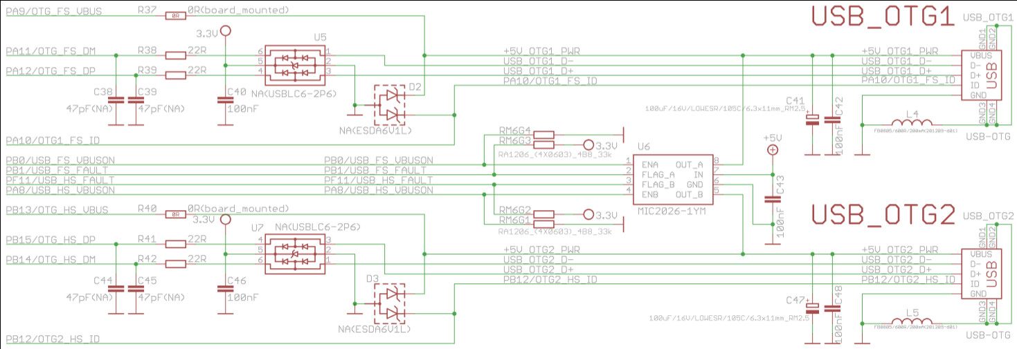
Markus Manninger schrieb:
> Eigentlich müsste der Code doch für beide Boards funktionieren, oder hab
> ich da was übersehen?

Ja die Hardwarebeschaltung beim USB bei STM32F4Discovery vs.
Olimexboard. Schaltpläne verlgeichen. Ich hab da noch was im Ohr, aber
nichts genaues mehr ...
so wie ich das sehe ist
VBUS-ON bei Discovery auf PC0 und beim Olimex auf PB0 !!

und auch darauf achten das die Quarz und PLL einstellung stimmt

Gruss Uwe
Also ich finde leider nix, wo das VBUS-ON Port konfiguriert wird. Die
restlichen I/Os werden in der Funktion USB_OTG_BSP_Init() in der Datei
usb_bsp.c konfiguriert:
1 | RCC_AHB1PeriphClockCmd( RCC_AHB1Periph_GPIOA , ENABLE); |
2 | |
3 | /* Configure SOF VBUS ID DM DP Pins */
|
4 | GPIO_InitStructure.GPIO_Pin = GPIO_Pin_8 | |
5 | GPIO_Pin_9 | |
6 | GPIO_Pin_11 | |
7 | GPIO_Pin_12; |
8 | |
9 | GPIO_InitStructure.GPIO_Speed = GPIO_Speed_100MHz; |
10 | GPIO_InitStructure.GPIO_Mode = GPIO_Mode_AF; |
11 | GPIO_InitStructure.GPIO_OType = GPIO_OType_PP; |
12 | GPIO_InitStructure.GPIO_PuPd = GPIO_PuPd_NOPULL ; |
13 | GPIO_Init(GPIOA, &GPIO_InitStructure); |
14 | |
15 | GPIO_PinAFConfig(GPIOA,GPIO_PinSource8,GPIO_AF_OTG1_FS) ; |
16 | GPIO_PinAFConfig(GPIOA,GPIO_PinSource9,GPIO_AF_OTG1_FS) ; |
17 | GPIO_PinAFConfig(GPIOA,GPIO_PinSource11,GPIO_AF_OTG1_FS) ; |
18 | GPIO_PinAFConfig(GPIOA,GPIO_PinSource12,GPIO_AF_OTG1_FS) ; |
19 | |
20 | /* this for ID line debug */
|
21 | |
22 | |
23 | GPIO_InitStructure.GPIO_Pin = GPIO_Pin_10; |
24 | GPIO_InitStructure.GPIO_OType = GPIO_OType_OD; |
25 | GPIO_InitStructure.GPIO_PuPd = GPIO_PuPd_UP; |
26 | GPIO_InitStructure.GPIO_Speed = GPIO_Speed_100MHz; |
27 | GPIO_Init(GPIOA, &GPIO_InitStructure); |
28 | GPIO_PinAFConfig(GPIOA,GPIO_PinSource10,GPIO_AF_OTG1_FS) ; |
29 | |
30 | RCC_APB2PeriphClockCmd(RCC_APB2Periph_SYSCFG, ENABLE); |
31 | RCC_AHB2PeriphClockCmd(RCC_AHB2Periph_OTG_FS, ENABLE) ; |
Jemand eine Idee?

lG,
Max
Hi,

ich hab jetzt nochmal nachgesehen,
das Signal von VBUS_Enable ist in deinem Fall egal
(CDC-Mode)

aber wie ich schon geschrieben habe stimmt die Frq-Einstellung nicht
das Demo ist für das Discovery-Board geschrieben
da ist ein Quarz von 8MHz verbaut
im Olimex Board ist es aber ein 12MHz Quarz

das bedeutet, du musst zwei Files abändern :

das File "stm32f4xx_conf.h" :

ist -> Zeile 29 : #define HSE_VALUE    ((uint32_t)8000000)
soll -> Zeile 29 : #define HSE_VALUE    ((uint32_t)12000000)


das File "system_stm32f4xx.c" :

ist -> Zeile 147 : #define PLL_M      8
soll ->Zeile 147 : #define PLL_M      12

dann sollte es funktionieren

oder du änderst den Quarz auf 8Mhz aus
(dann musst du nichts an der Software ändern)

Gruss Uwe
Danke,

Die Quarz relevanten Änderungen hab ich schon gemacht, leider tut sich
drotzdem nichts am USB Port.

Ich hab ja zwei USB Ports am Board, und ich möchte USB_OTG1 verwenden,
da dieser mit dem USB Port am Discovery compatibel sein sollte. Hänge
ich jetzt den Port auf den Rechner, tut sich absolut nix. Beim zweite
Port, sehe ich zumdest was am Bus:
1 | [590410.824019] usb 2-2: new full-speed USB device number 8 using uhci_hcd |
2 | [590410.944013] usb 2-2: device descriptor read/64, error -71 |
3 | [590411.168017] usb 2-2: device descriptor read/64, error -71 |
4 | [590411.384016] usb 2-2: new full-speed USB device number 9 using uhci_hcd |
5 | [590411.504015] usb 2-2: device descriptor read/64, error -71 |
6 | [590411.728016] usb 2-2: device descriptor read/64, error -71 |
7 | [590411.944014] usb 2-2: new full-speed USB device number 10 using uhci_hcd |
8 | [590412.352015] usb 2-2: device not accepting address 10, error -71 |
9 | [590412.464015] usb 2-2: new full-speed USB device number 11 using uhci_hcd |
10 | [590412.872013] usb 2-2: device not accepting address 11, error -71 |
11 | [590412.872024] hub 2-0:1.0: unable to enumerate USB device on port 2 |
Kann also sein dass ich die beiden Ports vertausche bzw. diese falsch
dokumentiert sind?

lG,
Max
hmmm...sehr sonderbar

prüf doch einfach mal die Verbindungsleitungen nach ob das ein Fehler in
der Doku ist

füge zum Test mal noch diese Zeile zur Initialisierung ein :

<code>
  GPIO_InitTypeDef GPIO_InitStructure;

  RCC_AHB1PeriphClockCmd(RCC_AHB1Periph_GPIOB , ENABLE);

  GPIO_InitStructure.GPIO_Pin = GPIO_Pin_0;
  GPIO_InitStructure.GPIO_Speed = GPIO_Speed_50MHz;
  GPIO_InitStructure.GPIO_Mode = GPIO_Mode_OUT;
  GPIO_InitStructure.GPIO_OType = GPIO_OType_PP;
  GPIO_InitStructure.GPIO_PuPd = GPIO_PuPd_NOPULL ;
  GPIO_Init(GPIOB,&GPIO_InitStructure);

  GPIO_SetBits(GPIOB, GPIO_Pin_0);
  // GPIO_ResetBits(GPIOB, GPIO_Pin_0);

</code>

ob Set oder Reset musst du ausprobieren
(k.A. ob Lo aktiv)

dann wüsste ich auch nichts mehr :-(
Juhuuu, es funktioniert. Die Dokumentation von Olimex ist diesebzüglich,
zumindestens für die Rev B1 des Boards, fehlerhaft. USB_OTG1 und
USB_OTG2 sind vertauscht.

lG,
Max
Bitte melde dich an um einen Beitrag zu schreiben. Anmeldung ist kostenlos und dauert nur eine Minute.
Bestehender Account
Schon ein Account bei Google/GoogleMail? Keine Anmeldung erforderlich!
Mit Google-Account einloggen
Mit Google-Account einloggen
Noch kein Account? Hier anmelden.