Meine Frage zielt auf den folgenden Thread  und das Zitat von heinz
Horst aus diesem ab:

Beitrag "TCP/IP Stack implementieren"

heinzhorst schrieb:
> Deinem Post entnehme ich, dass das Ganze auf einem Controller von
> Microchip laufen soll. Den TCP/IP stackt schreibst du dann natürlich
> nicht selbst, sondern verwendest den Fertigen von Microchip. Lade dir
> erstaal die Microchip Application Libraries runter. Da ist auch der
> Stack dabei und einige Beispielprojekte, die du als Grundlange verwenden
> kannst. Du kannst dann in der TCPConfig.h selbst einstellen, welche
> Komponenten vom Stack du benötigst, z.B. TCP, DHCP-Client, HTTP Server,
> Netbios, NTP, etc. Das MPFS-Image, also die Webseite, kannst du fest
> eincompillieren und so mit im Flash des Controllers ablegen. Nachteil:
> Du kannst die Webseite nicht im laufenden Betrieb ändern und benötigst
> auch entspreched viel Programmspeicher. Ein Controller mit 64k Flask
> sollte es da schon sein, besser 128k. Zweite Möglichkeit: Du kannst das
> MPFS-Image in einem externen SPI-EEPROM ablegen. Dann kannst du mit dem
> MPFS-Tool auch zur Laufzeit neue Images aufspielen.


Ich möchte ebenfalls einen Webserver entwickeln und diesen dann per
Browser abrufen können. Dies funktioniert mit dem WLAN-Modul MRF24W.h
von Microchip und einem PIC24.

Der TCP/IPStack ist vorgeben und ich versuche ihn auf meine gegebene
Hardware umzuschreiben, was schon mal kompliziert genug ist :)
Als erstes sollte eine einfache Ausgabe wie "Hello World" etc.
ausreichend sein und ich würde gerne den internen Speicher verwenden,
d.h. ich muss in TCPConfig.h das EEPROM und den SPI_Flash
auskommentieren. Das MPFS.s Image habe ich mit dem MPFS2 Tool schon
generiert. Meine Frage lautet nun wie ich dieses Image im
Programmspeicher eincompiliere.

Danke und Gruss
Im Stack werden die image.c und image.s eingebunden. Daher musst du
eigentlich nichts weiter machen, der Kompiler läd die also selbst mit
ins HEX-File.
mit image.c / .s meine ich die von die generierten MPFS Dateien.
Heisst das, dass ich das image.s nur im Projekt ablegen muss? Wenn ja wo
genau? Ich nutze zum Beispiel den EzConfig-Mode. Dann nur das image.s
unter (bei mir z.B) microchip solutions -> TCPIP -> WiFi EZConfig ->
EasyConfigWebpages ablegen? Also wo genau? Oder muss ich das image.s
noch im Source Code irgendwie includen?

Ich habe immer noch Schwierigkeiten den Stack "zum laufen" zu bringen.
Ich nutze vom MRF24 den PICTAIL Plus connecter sowie das PIC24E Starter
kit mit dem PIC32 Expansion Board.

Vielleicht kann mir nur jemand, der mit dem TCPIP Stack von Microchip
schon gearbeitet hat was zum grundsätzlichen ABlauf sagen.

Das Pictail stecke ich in den richtigen Slot des Expansion Board, so
dass ich SPI2 (inkl. SCK2, SDI2, SDO2, Chipselect, Reset des Moduls,
Interrupt und Hibernate) schon richtg "gematched" habe. D.h. also, dass
ich nach dem getting started des Moduls SPI2 nutzen soll. Ich möchte
gerne das Modul in den "SoftAP" - Modus versetzen, d.h. ich nutze den
WIFIEZConfig Mode.

Ich würde das Modul erstmal gerne zum laufen kriegen. Ich nutze also
SPI2 und muss verschiedene Features auskommentieren (z.B. alle LEDs und
Buttons, USE_LCD, USE_EEPROM und USE_SPI_Flash auskommentieren,
UART-Schnitstelle auskommentieren). Als Default_Network_Type nutze ich
den CFG_WF_Soft_AP (wie im getting started beschrieben). Was muss ich
weiterhin beachten? Der Compiler haut noch zig Fehlermeldungen raus.


Wenn mir jemand meine obige Frage bzgl. des image.s beantworten könnte
und eventuell was zum grundsätzlichen Ablauf für die Implementierung des
SOFT_AP Modus wäre ich dankbar. Wenn man zum ersten Mal mit dem TCPIP
Stack arbeitet fühlt man sich doch in wenig "erschlagen".

Danke und Gruss
Oder muss das image.s einfach den Source files über Add existing items
zugefügt werden?
Hi,
wenn du dir irgendein Beispielprojekt aus der MLA anschaust, wirst du
sehen, dass bei Dateien, die image.c und die image.s mit in den Sourcen
eingebunden sind. Standardmäßig liegen die Dateien einfach im
Projektordner.
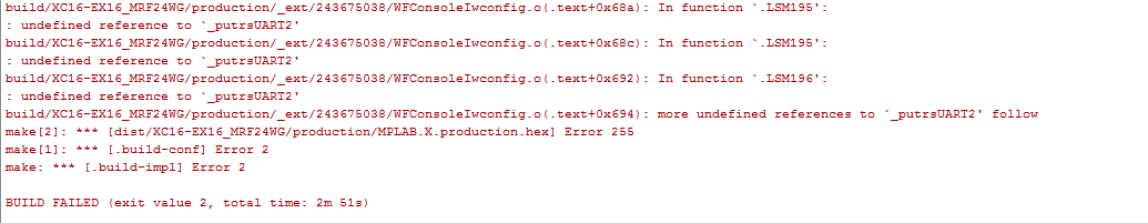
>>Der Compiler haut noch zig Fehlermeldungen raus.
Ja dann zeig die doch mal her.
was ich auch nicht ganz verstehe, was es mit

#define STACK_USE_MPFS2M

aus sich hat.

Bin mir unsicher ob ich das für meine beschriebene Anwendung
auskommentieren muss oder ob ich es benötige.
Angehängte Dateien:
-

WIFI-development-board-W490.jpg
85 KB -

PIC24_WebServer.jpg
150 KB
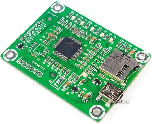
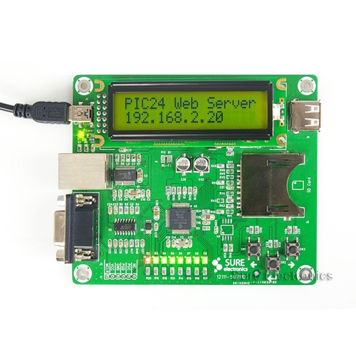
wuerde sich da nicht das Modul von Sure Electronics anbieten, dass
es gusntig in der Bucht gibt:

http://dangerousprototypes.com/2011/04/05/review-sure-electronics-wifi-web-server-module/

oder den PIC24 WebServer mit SD-Slot, aber ohne WiFi? (auch in der Bucht
ueber den Hersteller)

PS: Ich wusste leider nicht wie ich das doppelte Bild rausnehme :-(
:
Bearbeitet durch User
Die Boards sind sicherlich eine gute Alternative. Ich plane aber
irgendwann ne eigene Platine mit dem MRF24 Modul zu realisieren mit
deutlich mehr Peripherie und dann ist es ungünstig wenn ich das Modul
bzw. TCP/IP Stack nicht mal mit dem Starterkit zum laufen kriege.

Die Fehlermeldungen des obigen Compiler Ausschnitts bestehen immer noch.
Über Anregungen wäre ich dankbar.
Es steht doch dass die putUART Funtkion nicht gefunden wird. Das deutet
auf einen falschen include hin.


>>>#define STACK_USE_MPFS2M
MPFS2 brauchst du defintiv, die schaltet das "Dateisystem" ein, mit dem
die Webseiten abgespeichert werden. Was es genau mit dem M auf sich hat
weiß ich nicht.
Zeig mal die TCPIPconfig.h her
1 | * V5.36 ---- STACK_USE_MPFS support has been removed |
2 | ********************************************************************/ |
3 | #ifndef __TCPIPCONFIG_H
|
4 | #define __TCPIPCONFIG_H
|
5 | |
6 | #include "GenericTypeDefs.h" |
7 | #include "Compiler.h" |
8 | #define GENERATED_BY_TCPIPCONFIG "Version 1.0.3383.23374"
|
9 | |
10 | // =======================================================================
|
11 | // Application Options
|
12 | // =======================================================================
|
13 | |
14 | // Note: For the PIC24FJ128GA010, due to code memory limitations, the following items
|
15 | // must be commented out: STACK_USE_ZEROCONF_LINK_LOCAL, STACK_USE_DNS_SERVER,
|
16 | // STACK_USE_NBNS, STACK_USE_ANNOUNCE, STACK_USE_ICMP_CLIENT, STACK_USE_REBOOT_SERVER
|
17 | |
18 | /* Application Level Module Selection
|
19 | * Uncomment or comment the following lines to enable or
|
20 | * disabled the following high-level application modules.
|
21 | *
|
22 | * If certain compilations are enabled (eg STACK_USE_GENERIC_TCP_CLIENT_EXAMPLE),
|
23 | * check whether the files (eg GenericTCPClient.c) are located in folder (eg \TCPIP\WiFi EZConfig).
|
24 | * You may need to copy such files from the Demo App or WiFi Console folder.
|
25 | *
|
26 | */
|
27 | //#define STACK_USE_UART // Application demo using UART for IP address display and stack configuration
|
28 | //#define STACK_USE_UART2TCP_BRIDGE // UART to TCP Bridge application example
|
29 | //#define STACK_USE_IP_GLEANING
|
30 | #define STACK_USE_ICMP_SERVER // Ping query and response capability
|
31 | //#define STACK_USE_ICMP_CLIENT // Ping transmission capability
|
32 | #define STACK_USE_HTTP2_SERVER // New HTTP server with POST, Cookies, Authentication, etc.
|
33 | //#define STACK_USE_SSL_SERVER // SSL server socket support (Requires SW300052)
|
34 | //#define STACK_USE_SSL_CLIENT // SSL client socket support (Requires SW300052)
|
35 | //#define STACK_USE_AUTO_IP // Dynamic link-layer IP address automatic configuration protocol
|
36 | #define STACK_USE_DHCP_CLIENT // Dynamic Host Configuration Protocol client for obtaining IP address and other parameters
|
37 | #define STACK_USE_DHCP_SERVER // Single host DHCP server
|
38 | //#define STACK_USE_FTP_SERVER // File Transfer Protocol (old)
|
39 | //#define STACK_USE_SMTP_CLIENT // Simple Mail Transfer Protocol for sending email
|
40 | //#define STACK_USE_SNMP_SERVER // Simple Network Management Protocol v2C Community Agent
|
41 | //#define STACK_USE_SNMPV3_SERVER // Simple Network Management Protocol v3 Agent
|
42 | //#define STACK_USE_TFTP_CLIENT // Trivial File Transfer Protocol client
|
43 | //#define STACK_USE_GENERIC_TCP_CLIENT_EXAMPLE // HTTP Client example in GenericTCPClient.c. If using EZConfig, need to copy this file from Demo App or WiFi Console.
|
44 | //#define STACK_USE_GENERIC_TCP_SERVER_EXAMPLE // ToUpper server example in GenericTCPServer.c. If using EZConfig, need to copy this file from Demo App or WiFi Console.
|
45 | //#define STACK_USE_TELNET_SERVER // Telnet server
|
46 | //#define STACK_USE_ANNOUNCE // Microchip Embedded Ethernet Device Discoverer server/client
|
47 | #define STACK_USE_DNS // Domain Name Service Client for resolving hostname strings to IP addresses
|
48 | //#define STACK_USE_DNS_SERVER // Domain Name Service Server for redirection to the local device
|
49 | //#define STACK_USE_NBNS // NetBIOS Name Service Server for repsonding to NBNS hostname broadcast queries
|
50 | //#define STACK_USE_REBOOT_SERVER // Module for resetting this PIC remotely. Primarily useful for a Bootloader.
|
51 | //#define STACK_USE_SNTP_CLIENT // Simple Network Time Protocol for obtaining current date/time from Internet
|
52 | //#define STACK_USE_UDP_PERFORMANCE_TEST // Module for testing UDP TX performance characteristics. NOTE: Enabling this will cause a huge amount of UDP broadcast packets to flood your network on the discard port. Use care when enabling this on production networks, especially with VPNs (could tunnel broadcast traffic across a limited bandwidth connection).
|
53 | //#define STACK_USE_TCP_PERFORMANCE_TEST // Module for testing TCP TX performance characteristics
|
54 | //#define STACK_USE_DYNAMICDNS_CLIENT // Dynamic DNS client updater module
|
55 | //#define STACK_USE_BERKELEY_API // Berekely Sockets APIs are available
|
56 | |
57 | //#define STACK_USE_ZEROCONF_LINK_LOCAL // Zeroconf IPv4 Link-Local Addressing
|
58 | #define STACK_USE_ZEROCONF_MDNS_SD // Zeroconf mDNS and mDNS service discovery
|
59 | #if defined(CFG_INCLUDE_EX16_MRF24WG) && defined(__C32__)
|
60 | //#define STACK_USE_TCP_MOBILE_APP_SERVER // This is valid only with Explorer16 eval board and MRF24WG Wi-Fi module
|
61 | #ifdef STACK_USE_TCP_MOBILE_APP_SERVER
|
62 | #ifndef STACK_USE_ZEROCONF_LINK_LOCAL && !defined(__PIC24FJ128GA010__)
|
63 | //#define STACK_USE_ZEROCONF_LINK_LOCAL // Zeroconf IPv4 Link-Local Addressing
|
64 | #endif
|
65 | #ifndef STACK_USE_ZEROCONF_MDNS_SD
|
66 | #define STACK_USE_ZEROCONF_MDNS_SD // Zeroconf mDNS and mDNS service discovery
|
67 | #endif
|
68 | #endif /* STACK_USE_TCP_MOBILE_APP_SERVER */ |
69 | #endif /* CFG_INCLUDE_EX16_MRF24WG */ |
70 | |
71 | // =======================================================================
|
72 | // Data Storage Options
|
73 | // =======================================================================
|
74 | |
75 | /* MPFS Configuration
|
76 | * MPFS is automatically included when required for other
|
77 | * applications. If your custom application requires it
|
78 | * otherwise, uncomment the appropriate selection.
|
79 | */
|
80 | #define STACK_USE_MPFS2
|
81 | |
82 | /* MPFS Storage Location
|
83 | * If html pages are stored in internal program memory,
|
84 | * comment both MPFS_USE_EEPROM and MPFS_USE_SPI_FLASH, then
|
85 | * include an MPFS image (.c or .s file) in the project.
|
86 | * If html pages are stored in external memory, uncomment the
|
87 | * appropriate definition.
|
88 | *
|
89 | * Supported serial flash parts include the SST25VFxxxB series.
|
90 | */
|
91 | //#define MPFS_USE_EEPROM
|
92 | //#define MPFS_USE_SPI_FLASH
|
93 | |
94 | /* EEPROM Addressing Selection
|
95 | * If using the 1Mbit EEPROM, uncomment this line
|
96 | */
|
97 | //#define USE_EEPROM_25LC1024
|
98 | |
99 | /* EEPROM Reserved Area
|
100 | * Number of EEPROM bytes to be reserved before MPFS storage starts.
|
101 | * These bytes host application configurations such as IP Address,
|
102 | * MAC Address, and any other required variables.
|
103 | *
|
104 | * For MPFS Classic, this setting must match the Reserved setting
|
105 | * on the Advanced Settings page of the MPFS2 Utility.
|
106 | */
|
107 | #define MPFS_RESERVE_BLOCK (205ul)
|
108 | |
109 | /* MPFS File Handles
|
110 | * Maximum number of simultaneously open MPFS2 files.
|
111 | * For MPFS Classic, this has no effect.
|
112 | */
|
113 | #define MAX_MPFS_HANDLES (7ul)
|
114 | |
115 | |
116 | // =======================================================================
|
117 | // Network Addressing Options
|
118 | // =======================================================================
|
119 | |
120 | /* Default Network Configuration
|
121 | * These settings are only used if data is not found in EEPROM.
|
122 | * To clear EEPROM, hold BUTTON0, reset the board, and continue
|
123 | * holding until the LEDs flash. Release, and reset again.
|
124 | */
|
125 | #define MY_DEFAULT_HOST_NAME "MCHPBOARD"
|
126 | |
127 | #define MY_DEFAULT_MAC_BYTE1 (0x00) // Use the default of 00-04-A3-00-00-00
|
128 | #define MY_DEFAULT_MAC_BYTE2 (0x04) // if using an ENCX24J600, MRF24W, or
|
129 | #define MY_DEFAULT_MAC_BYTE3 (0xA3) // PIC32MX6XX/7XX internal Ethernet
|
130 | #define MY_DEFAULT_MAC_BYTE4 (0x00) // controller and wish to use the
|
131 | #define MY_DEFAULT_MAC_BYTE5 (0x00) // internal factory programmed MAC
|
132 | #define MY_DEFAULT_MAC_BYTE6 (0x00) // address instead.
|
133 | |
134 | #define MY_DEFAULT_IP_ADDR_BYTE1 (169ul)
|
135 | #define MY_DEFAULT_IP_ADDR_BYTE2 (254ul)
|
136 | #define MY_DEFAULT_IP_ADDR_BYTE3 (1ul)
|
137 | #define MY_DEFAULT_IP_ADDR_BYTE4 (1ul)
|
138 | |
139 | #define MY_DEFAULT_MASK_BYTE1 (255ul)
|
140 | #define MY_DEFAULT_MASK_BYTE2 (255ul)
|
141 | #define MY_DEFAULT_MASK_BYTE3 (0ul)
|
142 | #define MY_DEFAULT_MASK_BYTE4 (0ul)
|
143 | |
144 | #define MY_DEFAULT_GATE_BYTE1 (169ul)
|
145 | #define MY_DEFAULT_GATE_BYTE2 (254ul)
|
146 | #define MY_DEFAULT_GATE_BYTE3 (1ul)
|
147 | #define MY_DEFAULT_GATE_BYTE4 (1ul)
|
148 | |
149 | #define MY_DEFAULT_PRIMARY_DNS_BYTE1 (169ul)
|
150 | #define MY_DEFAULT_PRIMARY_DNS_BYTE2 (254ul)
|
151 | #define MY_DEFAULT_PRIMARY_DNS_BYTE3 (1ul)
|
152 | #define MY_DEFAULT_PRIMARY_DNS_BYTE4 (1ul)
|
153 | |
154 | #define MY_DEFAULT_SECONDARY_DNS_BYTE1 (0ul)
|
155 | #define MY_DEFAULT_SECONDARY_DNS_BYTE2 (0ul)
|
156 | #define MY_DEFAULT_SECONDARY_DNS_BYTE3 (0ul)
|
157 | #define MY_DEFAULT_SECONDARY_DNS_BYTE4 (0ul)
|
158 | |
159 | // =======================================================================
|
160 | // PIC32MX7XX/6XX MAC Layer Options
|
161 | // If not using a PIC32MX7XX/6XX device, ignore this section.
|
162 | // =======================================================================
|
163 | #define ETH_CFG_LINK 0 // set to 1 if you need to config the link to specific following parameters
|
164 | // otherwise the default connection will be attempted
|
165 | // depending on the selected PHY
|
166 | #define ETH_CFG_AUTO 1 // use auto negotiation
|
167 | #define ETH_CFG_10 1 // use/advertise 10 Mbps capability
|
168 | #define ETH_CFG_100 1 // use/advertise 100 Mbps capability
|
169 | #define ETH_CFG_HDUPLEX 1 // use/advertise half duplex capability
|
170 | #define ETH_CFG_FDUPLEX 1 // use/advertise full duplex capability
|
171 | #define ETH_CFG_AUTO_MDIX 1 // use/advertise auto MDIX capability
|
172 | #define ETH_CFG_SWAP_MDIX 1 // use swapped MDIX. else normal MDIX
|
173 | |
174 | #define EMAC_TX_DESCRIPTORS 2 // number of the TX descriptors to be created
|
175 | #define EMAC_RX_DESCRIPTORS 8 // number of the RX descriptors and RX buffers to be created
|
176 | |
177 | #define EMAC_RX_BUFF_SIZE 1536 // size of a RX buffer. should be multiple of 16
|
178 | // this is the size of all receive buffers processed by the ETHC
|
179 | // The size should be enough to accomodate any network received packet
|
180 | // If the packets are larger, they will have to take multiple RX buffers
|
181 | // The current implementation does not handle this situation right now and the packet is discarded.
|
182 | |
183 | |
184 | // =======================================================================
|
185 | // Transport Layer Options
|
186 | // =======================================================================
|
187 | |
188 | /* Transport Layer Configuration
|
189 | * The following low level modules are automatically enabled
|
190 | * based on module selections above. If your custom module
|
191 | * requires them otherwise, enable them here.
|
192 | */
|
193 | #define STACK_USE_TCP
|
194 | #define STACK_USE_UDP
|
195 | |
196 | /* Client Mode Configuration
|
197 | * Uncomment following line if this stack will be used in CLIENT
|
198 | * mode. In CLIENT mode, some functions specific to client operation
|
199 | * are enabled.
|
200 | */
|
201 | #if defined(STACK_USE_DHCP_CLIENT) || defined(STACK_USE_ICMP_CLIENT)
|
202 | #define STACK_CLIENT_MODE
|
203 | #endif
|
204 | |
205 | /* TCP Socket Memory Allocation
|
206 | * TCP needs memory to buffer incoming and outgoing data. The
|
207 | * amount and medium of storage can be allocated on a per-socket
|
208 | * basis using the example below as a guide.
|
209 | */
|
210 | // Allocate how much total RAM (in bytes) you want to allocate
|
211 | // for use by your TCP TCBs, RX FIFOs, and TX FIFOs.
|
212 | #define TCP_ETH_RAM_SIZE (8192ul)
|
213 | #define TCP_PIC_RAM_SIZE (0ul)
|
214 | #define TCP_SPI_RAM_SIZE (0ul)
|
215 | #define TCP_SPI_RAM_BASE_ADDRESS (0x00)
|
216 | |
217 | // Define names of socket types
|
218 | #define TCP_SOCKET_TYPES
|
219 | #define TCP_PURPOSE_GENERIC_TCP_CLIENT 0
|
220 | #define TCP_PURPOSE_GENERIC_TCP_SERVER 1
|
221 | #define TCP_PURPOSE_TELNET 2
|
222 | #define TCP_PURPOSE_FTP_COMMAND 3
|
223 | #define TCP_PURPOSE_FTP_DATA 4
|
224 | #define TCP_PURPOSE_TCP_PERFORMANCE_TX 5
|
225 | #define TCP_PURPOSE_TCP_PERFORMANCE_RX 6
|
226 | #define TCP_PURPOSE_UART_2_TCP_BRIDGE 7
|
227 | #define TCP_PURPOSE_HTTP_SERVER 8
|
228 | #define TCP_PURPOSE_DEFAULT 9
|
229 | #define TCP_PURPOSE_BERKELEY_SERVER 10
|
230 | #define TCP_PURPOSE_BERKELEY_CLIENT 11
|
231 | #define TCP_PURPOSE_MOBILE_APP_SERVER 12
|
232 | #define END_OF_TCP_SOCKET_TYPES
|
233 | |
234 | #if defined(__TCP_C)
|
235 | // Define what types of sockets are needed, how many of
|
236 | // each to include, where their TCB, TX FIFO, and RX FIFO
|
237 | // should be stored, and how big the RX and TX FIFOs should
|
238 | // be. Making this initializer bigger or smaller defines
|
239 | // how many total TCP sockets are available.
|
240 | //
|
241 | // Each socket requires up to 56 bytes of PIC RAM and
|
242 | // 48+(TX FIFO size)+(RX FIFO size) bytes of TCP_*_RAM each.
|
243 | //
|
244 | // Note: The RX FIFO must be at least 1 byte in order to
|
245 | // receive SYN and FIN messages required by TCP. The TX
|
246 | // FIFO can be zero if desired.
|
247 | #define TCP_CONFIGURATION
|
248 | ROM struct |
249 | {
|
250 | BYTE vSocketPurpose; |
251 | BYTE vMemoryMedium; |
252 | WORD wTXBufferSize; |
253 | WORD wRXBufferSize; |
254 | } TCPSocketInitializer[] = |
255 | {
|
256 | {TCP_PURPOSE_GENERIC_TCP_CLIENT, TCP_ETH_RAM, 1024, 20}, |
257 | {TCP_PURPOSE_GENERIC_TCP_SERVER, TCP_ETH_RAM, 20, 1024}, |
258 | //{TCP_PURPOSE_TELNET, TCP_ETH_RAM, 200, 150},
|
259 | //{TCP_PURPOSE_TELNET, TCP_ETH_RAM, 200, 150},
|
260 | //{TCP_PURPOSE_TELNET, TCP_ETH_RAM, 200, 150},
|
261 | //{TCP_PURPOSE_FTP_COMMAND, TCP_ETH_RAM, 100, 40},
|
262 | //{TCP_PURPOSE_FTP_DATA, TCP_ETH_RAM, 0, 128},
|
263 | //{TCP_PURPOSE_TCP_PERFORMANCE_TX, TCP_ETH_RAM, 200, 1},
|
264 | //{TCP_PURPOSE_TCP_PERFORMANCE_RX, TCP_ETH_RAM, 40, 1500},
|
265 | //{TCP_PURPOSE_UART_2_TCP_BRIDGE, TCP_ETH_RAM, 256, 256},
|
266 | {TCP_PURPOSE_HTTP_SERVER, TCP_ETH_RAM, 1000, 1000}, |
267 | {TCP_PURPOSE_HTTP_SERVER, TCP_ETH_RAM, 1000, 1000}, |
268 | #if defined(STACK_USE_TCP_MOBILE_APP_SERVER)
|
269 | {TCP_PURPOSE_MOBILE_APP_SERVER, TCP_ETH_RAM, 1000, 1000}, |
270 | #endif
|
271 | //{TCP_PURPOSE_DEFAULT, TCP_ETH_RAM, 1000, 1000},
|
272 | //{TCP_PURPOSE_BERKELEY_SERVER, TCP_ETH_RAM, 25, 20},
|
273 | //{TCP_PURPOSE_BERKELEY_SERVER, TCP_ETH_RAM, 25, 20},
|
274 | //{TCP_PURPOSE_BERKELEY_SERVER, TCP_ETH_RAM, 25, 20},
|
275 | //{TCP_PURPOSE_BERKELEY_CLIENT, TCP_ETH_RAM, 125, 100},
|
276 | };
|
277 | #define END_OF_TCP_CONFIGURATION
|
278 | #endif
|
279 | |
280 | /* UDP Socket Configuration
|
281 | * Define the maximum number of available UDP Sockets, and whether
|
282 | * or not to include a checksum on packets being transmitted.
|
283 | */
|
284 | #define MAX_UDP_SOCKETS (8u)
|
285 | //#define UDP_USE_TX_CHECKSUM // This slows UDP TX performance by nearly 50%, except when using the ENCX24J600 or PIC32MX6XX/7XX, which have a super fast DMA and incurs virtually no speed pentalty.
|
286 | |
287 | |
288 | /* Berkeley API Sockets Configuration
|
289 | * Note that each Berkeley socket internally uses one TCP or UDP socket
|
290 | * defined by MAX_UDP_SOCKETS and the TCPSocketInitializer[] array.
|
291 | * Therefore, this number MUST be less than or equal to MAX_UDP_SOCKETS + the
|
292 | * number of TCP sockets defined by the TCPSocketInitializer[] array
|
293 | * (i.e. sizeof(TCPSocketInitializer)/sizeof(TCPSocketInitializer[0])).
|
294 | * This define has no effect if STACK_USE_BERKELEY_API is not defined and
|
295 | * Berkeley Sockets are disabled. Set this value as low as your application
|
296 | * requires to avoid waisting RAM.
|
297 | */
|
298 | #define BSD_SOCKET_COUNT (5u)
|
299 | |
300 | |
301 | // =======================================================================
|
302 | // Application-Specific Options
|
303 | // =======================================================================
|
304 | |
305 | // -- HTTP2 Server options -----------------------------------------------
|
306 | |
307 | // Maximum numbers of simultaneous HTTP connections allowed.
|
308 | // Each connection consumes 2 bytes of RAM and a TCP socket
|
309 | #define MAX_HTTP_CONNECTIONS (2u)
|
310 | |
311 | // Optional setting to use PIC RAM instead of Ethernet/Wi-Fi RAM for
|
312 | // storing HTTP Connection Context variables (HTTP_CONN structure for each
|
313 | // HTTP connection). Undefining this macro results in the Ethernet/Wi-Fi
|
314 | // RAM being used (minimum PIC RAM usage, lower performance). Defining
|
315 | // this macro results in PIC RAM getting used (higher performance, but uses
|
316 | // PIC RAM). This option should not be enabled on PIC18 devices. The
|
317 | // performance increase of having this option defined is only apparent when
|
318 | // the HTTP server is servicing multiple connections simultaneously.
|
319 | //#define HTTP_SAVE_CONTEXT_IN_PIC_RAM
|
320 | |
321 | // Indicate what file to serve when no specific one is requested
|
322 | #define HTTP_DEFAULT_FILE "index.htm"
|
323 | #define HTTPS_DEFAULT_FILE "index.htm"
|
324 | #define HTTP_DEFAULT_LEN (10u) // For buffer overrun protection.
|
325 | // Set to longest length of above two strings.
|
326 | |
327 | // Configure MPFS over HTTP updating
|
328 | // Comment this line to disable updating via HTTP
|
329 | #define HTTP_MPFS_UPLOAD "mpfsupload"
|
330 | //#define HTTP_MPFS_UPLOAD_REQUIRES_AUTH // Require password for MPFS uploads
|
331 | // Certain firewall and router combinations cause the MPFS2 Utility to fail
|
332 | // when uploading. If this happens, comment out this definition.
|
333 | |
334 | // Define which HTTP modules to use
|
335 | // If not using a specific module, comment it to save resources
|
336 | #define HTTP_USE_POST // Enable POST support
|
337 | //#define HTTP_USE_COOKIES // Enable cookie support
|
338 | //#define HTTP_USE_AUTHENTICATION // Enable basic authentication support
|
339 | |
340 | //#define HTTP_NO_AUTH_WITHOUT_SSL // Uncomment to require SSL before requesting a password
|
341 | |
342 | // Define the listening port for the HTTP server
|
343 | #define HTTP_PORT (80u)
|
344 | |
345 | // Define the listening port for the HTTPS server (if STACK_USE_SSL_SERVER is enabled)
|
346 | #define HTTPS_PORT (443u)
|
347 | |
348 | // Define the maximum data length for reading cookie and GET/POST arguments (bytes)
|
349 | #define HTTP_MAX_DATA_LEN (100u)
|
350 | |
351 | // Define the minimum number of bytes free in the TX FIFO before executing callbacks
|
352 | #define HTTP_MIN_CALLBACK_FREE (16u)
|
353 | |
354 | //#define STACK_USE_HTTP_APP_RECONFIG // Use the AppConfig web page in the Demo App (~2.5kb ROM, ~0b RAM)
|
355 | //#define STACK_USE_HTTP_MD5_DEMO // Use the MD5 Demo web page (~5kb ROM, ~160b RAM)
|
356 | //#define STACK_USE_HTTP_EMAIL_DEMO // Use the e-mail demo web page
|
357 | |
358 | // -- SSL Options --------------------------------------------------------
|
359 | |
360 | #define MAX_SSL_CONNECTIONS (2ul) // Maximum connections via SSL
|
361 | #define MAX_SSL_SESSIONS (2ul) // Max # of cached SSL sessions
|
362 | #define MAX_SSL_BUFFERS (4ul) // Max # of SSL buffers (2 per socket)
|
363 | #define MAX_SSL_HASHES (5ul) // Max # of SSL hashes (2 per, plus 1 to avoid deadlock)
|
364 | |
365 | // Bits in SSL RSA key. This parameter is used for SSL sever
|
366 | // connections only. The only valid value is 512 bits (768 and 1024
|
367 | // bits do not work at this time). Note, however, that SSL client
|
368 | // operations do currently work up to 1024 bit RSA key length.
|
369 | #define SSL_RSA_KEY_SIZE (512ul)
|
370 | |
371 | |
372 | // -- Telnet Options -----------------------------------------------------
|
373 | |
374 | // Number of simultaneously allowed Telnet sessions. Note that you
|
375 | // must have an equal number of TCP_PURPOSE_TELNET type TCP sockets
|
376 | // declared in the TCPSocketInitializer[] array above for multiple
|
377 | // connections to work. If fewer sockets are available than this
|
378 | // definition, then the the lesser of the two quantities will be the
|
379 | // actual limit.
|
380 | #define MAX_TELNET_CONNECTIONS (1u)
|
381 | |
382 | // Default local listening port for the Telnet server. Port 23 is the
|
383 | // protocol default.
|
384 | #define TELNET_PORT 23
|
385 | |
386 | // Default local listening port for the Telnet server when SSL secured.
|
387 | // Port 992 is the telnets protocol default.
|
388 | #define TELNETS_PORT 992
|
389 | |
390 | // Force all connecting clients to be SSL secured and connected via
|
391 | // TELNETS_PORT. Connections on port TELNET_PORT will be ignored. If
|
392 | // STACK_USE_SSL_SERVER is undefined, this entire setting is ignored
|
393 | // (server will accept unsecured connections on TELNET_PORT and won't even
|
394 | // listen on TELNETS_PORT).
|
395 | //#define TELNET_REJECT_UNSECURED
|
396 | |
397 | // Default username and password required to login to the Telnet server.
|
398 | #define TELNET_USERNAME "admin"
|
399 | #define TELNET_PASSWORD "microchip"
|
400 | |
401 | |
402 | // -- SNMP Options -------------------------------------------------------
|
403 | |
404 | // Comment following line if SNMP TRAP support is needed
|
405 | //#define SNMP_TRAP_DISABLED
|
406 | |
407 | //#define SNMP_STACK_USE_V2_TRAP
|
408 | #if defined(STACK_USE_SNMPV3_SERVER)
|
409 | #define SNMP_V1_V2_TRAP_WITH_SNMPV3
|
410 | #endif
|
411 | |
412 | // This is the maximum length for community string.
|
413 | // Application must ensure that this length is observed.
|
414 | // SNMP module adds one byte extra after SNMP_COMMUNITY_MAX_LEN
|
415 | // for adding '\0' NULL character.
|
416 | #define SNMP_COMMUNITY_MAX_LEN (8u)
|
417 | #define SNMP_MAX_COMMUNITY_SUPPORT (3u)
|
418 | #define NOTIFY_COMMUNITY_LEN (SNMP_COMMUNITY_MAX_LEN)
|
419 | |
420 | // Default SNMPv2C community names. These can be overridden at run time if
|
421 | // alternate strings are present in external EEPROM or Flash (actual
|
422 | // strings are stored in AppConfig.readCommunity[] and
|
423 | // AppConfig.writeCommunity[] arrays). These strings are case sensitive.
|
424 | // An empty string means disabled (not matchable).
|
425 | // For application security, these default community names should not be
|
426 | // used, but should all be disabled to force the end user to select unique
|
427 | // community names. These defaults are provided only to make it easier to
|
428 | // start development. Specifying more strings than
|
429 | // SNMP_MAX_COMMUNITY_SUPPORT will result in the later strings being
|
430 | // ignored (but still wasting program memory). Specifying fewer strings is
|
431 | // legal, as long as at least one is present. A string larger than
|
432 | // SNMP_COMMUNITY_MAX_LEN bytes will be ignored.
|
433 | #define SNMP_READ_COMMUNITIES {"public", "read", ""}
|
434 | #define END_OF_SNMP_READ_COMMUNITIES
|
435 | #define SNMP_WRITE_COMMUNITIES {"private", "write", "public"}
|
436 | #define END_OF_SNMP_WRITE_COMMUNITIES
|
437 | #endif
|
Wenn du die Demo nutzt musst du zumindest den UART mit reinkompilieren.
OK schon mal Danke für die Hilfe. Jetzt bekomme ich zwar noch ein paar
Warnungen, aber ich kann "Suuccesful" compilieren.

Jetzt noch
1 | #define MY_DEFAULT_NETWORK_TYPE CFG_WF_SOFT_AP
|
und den Pictail Plus Connector in den mittleren Slot Vom J4 Connector
des PIC32 Expansion Board stecken.

So müsste SPI2
(also
1 | #define MRF24W_IN_SPI2
|
)

perfekt gematched sein. D.h. Chipselect des Moduls auf G9, SDI auf G7,
SCK auf G6 usw.

Wenn ich jetzt jetzt das Device proagrammiere hätte ich erwartet, dass
es funktioniert, d.h. dass das Modul nen AP macht und ich unter
Drahtlosverbindungen die SSID (in diesem Fall MCHPSoftAP) finde und mich
connecten kann. Leider sehe ich gar nichts :(

Jemand ne Idee was ich nicht beachtet habe??
I getting started steht, dass das Modul immer versucht die letzte
Verbindung wieder anzunehmen und das man bei Restart den But S3 (dies
ist bei mir auf dem USB Starter kit der BUT S1) 4 Sekunden drücken muss.
Hier passiert auch nix.

Über Anregungen wäre ich wiederum dankbar!
Niemand außer Stampede, der sich mit dem TCP/IP Stack auskennt?
Versuche, die RS232 der TCPIP Stacks anzuzapfen. Der Stack (v.a. der
WIFI Teil) gibt da sehr hilfreiche Infos aus.
Ob der SPI2 der richtige ist, keine Ahnung das wirst nur du wissen. Was
allerdings wichtig ist, ist dass die Interrupts PINs korrekt sind. Ohne
die funktioniert der MRF nicht (das Programm bleibt irgendwo in der Init
hängen).
Hast du einen Debugger? Dann guck doch mal was das Programm macht.
Schon mal vielen Dank, dass Du immer noch nicht aufgegeben hast :)

Stampede schrieb:
> Versuche, die RS232 der TCPIP Stacks anzuzapfen. Der Stack (v.a.
> der
> WIFI Teil) gibt da sehr hilfreiche Infos aus.

Das geht leider nicht (bzw. nur mit großem Aufwand, da das PIC32
Expansion Board keine serielle Schnittstelle hat und ich irgendwas
größeres mit nem Pegelwandler basteln müsste.

Stampede schrieb:

> Ob der SPI2 der richtige ist, keine Ahnung das wirst nur du wissen. Was
> allerdings wichtig ist, ist dass die Interrupts PINs korrekt sind. Ohne
> die funktioniert der MRF nicht (das Programm bleibt irgendwo in der Init

Habe das alles nochmals nachgrprüft und es passt zu 100%. Gerade der
Interrput PIN liegt auf RA14 und entspricht genau der gegebenen SPI2
Vorkonfiguration. Da dürfte das PIC32 Expansion Board mit dem Explorer
16 identisch sein.

Ich bin gerade am debuggen und das Programm durchläuft InitializeBoard()
(obwohl da ja nur LEDs und BUT gesetzt werden, die ich gar nicht
benötige), danach auch TickInit() und MPFSInit() (hier müsste das Image
geladen werden und das Programm sprint in der Tat in meine image.s und
durchläuft den Programmcode
1 | _ReadProgramMemory:
|
2 | push _TBLPAG |
3 | mov w1,_TBLPAG |
4 | mov w0,w5 |
5 | tblrdl [w5],w0 |
6 | tblrdh [w5],w1 |
7 | pop _TBLPAG |
8 | return
|
)

Weiterhin werden die Funktion Validate() und MPFSGetArray() durchlaufen.
Anschließend die InitAppconfig (inkl. FormatNetBIOSName() und
CalcIPChecksum(BYTE* buffer, WORD count)).Dann kommt die StackInit().
Wenn ich einen Breakpoint hinter die StackInit() setze sprint das
Programm nie auf diesen, sondern befindet sich immer im Zusatnd
"Running". Bis zu dem Breakpoint kurz vor dieser Funktion läuft alles
reibungslos. Ich vermute also dass es sich irgendwo in dieser Funktion
in einer Endlosschleife etc. befindet, habe aber ka woran das liegen
könnte????? Problem ist, dass in diesr Funktion auch noch sehr viele
Funktionen ineinander verschalchtelt sind!
>Ich vermute also dass es sich irgendwo in dieser Funktion
>in einer Endlosschleife etc. befindet, habe aber ka woran das liegen
>könnte????? Problem ist, dass in diesr Funktion auch noch sehr viele
>Funktionen ineinander verschalchtelt sind!
Korrekt, der Stack bleibt bei der Init also stecken. Dann musst du dich
mit den Breakpoints bzw dem Animate so lange durchhangeln, bis du siehst
wo er steckenbleibt. Eine andere Möglichkeit gibt es leider nicht.
also der "Fehler" muss irgendo im Programmteil des Anhanges liegen (in
der Helpers.c, die in Stackinit() aufgerufen wird). Der untere
Breakpoint wird NIE Erreicht. Stattdessen springt das Programm in die
Funktion LFSRSeedRand(DWORD dwSeed) arbeitet die for Schleife ab, dann
in die Fkt. LFSRRand(void) und arbeitet ebenso die for Schleife ab und
bleibt dann meines Verständnisses in Zeile 316 von Helpers.c hängen.

Nämlich dem folgenden Code:
while(1)
  {
    ClrWdt();
    #if defined(_C30_)
      while(!IFS0bits.AD1IF); <- hier!!!
    #else
      while(!IFS1bits.AD1IF);
    #endif
    wTime = TMR1;
    TMR1 = 0x0000;

[/c]

D.h. er sprint erst raus wenn das Interuppt Flag gesetzt wird!
Habe noch einen letzten Punkt:

Die Funktion WF_AssertionFailed(UINT8 moduleNumber, UINT16 lineNumber)
gibt mir gibt mir folgenden Fehler zurück:

if (TickGet() - startTickCount >= maxAllowedTicks)
        {
            WF_ASSERT(FALSE);
        }

Welche Configuration Bits nutzt Ihr? Interner Oscillator mit PLL? 80MHz
Oscillator Frequenz dür 40MHz Input Clock.

Ich muss diese halt neu setzen, da der PIC des Starterkits vom Stack
nicht unterstützt wird.

Dies könnte auf jeden Fall das Problem sein, dass ich die Configuration
Bits nicht richtig gesetzt habe!
Hi,

Ich hatte auch mal Probleme mit dem Stack in Verbindung mit dem ADC und
der Seed Funktion. Dsa Problem war, dass ich den ADC noch außerhalb vom
TCPIP Stack noch benutzt habe. Mit dem Ergebnis, dass das IF Flag extern
zurückgesetzt wurde.
Es gibt nun 2 zwei Möglichkeiten:

1. Das Flag ändert sich nicht weil die Taktrate es ADC falsch ist. Unten
hab ich mal meine Konfig angehängt, 80MHz CPU und Peripherie. Damit
sollte der ADC richtig initalisiert sein. (8MHz Quarz)
2. Deine Demo nutzt irgendwo anderen ADC Kram, der das Flag rücksetzt.

>Die Funktion WF_AssertionFailed(UINT8 moduleNumber, UINT16 lineNumber)
>gibt mir gibt mir folgenden Fehler zurück: [...]
>WF_ASSERT(FALSE);

Das kann auch ein Fehler in der SPI Schnittstelle sein. Der Stack greift
auf den MRF24 per SPI zu, am Ende wartet der üblicherweise darauf, dass
die Daten quittiert werden. Das waren (wenn ich mich richtig erinnere)
teilweise rückgelesene Daten aus dem MRF24, zudem erwaretet der Stack
auch noch Interrupts über die INT-Leitung. Details musste man in den
Sourcen nachgucken.
1 | // Set configuration fuses (but only in MainDemo.c where THIS_IS_STACK_APPLICATION is defined)
|
2 | #if defined(THIS_IS_STACK_APPLICATION)
|
3 | /** CONFIGURATION **************************************************/
|
4 | #pragma config UPLLEN = ON // USB PLL Enabled
|
5 | #pragma config FPLLMUL = MUL_20 // PLL Multiplier
|
6 | #pragma config UPLLIDIV = DIV_2 // USB PLL Input Divider
|
7 | #pragma config FPLLIDIV = DIV_2 // PLL Input Divider
|
8 | #pragma config FPLLODIV = DIV_1 // PLL Output Divider
|
9 | #pragma config FPBDIV = DIV_1 // Peripheral Clock divisor
|
10 | #pragma config FWDTEN = OFF // Watchdog Timer
|
11 | #pragma config WDTPS = PS1 // Watchdog Timer Postscale
|
12 | #pragma config FCKSM = CSECME // Clock Switching & Fail Safe Clock Monitor
|
13 | #pragma config OSCIOFNC = OFF // CLKO Enable
|
14 | #pragma config POSCMOD = XT // Primary Oscillator
|
15 | #pragma config IESO = OFF // Internal/External Switch-over
|
16 | #pragma config FSOSCEN = ON // Secondary Oscillator Enable (KLO was off)
|
17 | #pragma config FNOSC = PRIPLL // Oscillator Selection
|
18 | #pragma config CP = OFF // Code Protect
|
19 | #pragma config BWP = OFF // Boot Flash Write Protect
|
20 | #pragma config PWP = OFF // Program Flash Write Protect
|
21 | #pragma config ICESEL = ICS_PGx2 // ICE/ICD Comm Channel Select
|
22 | #pragma config DEBUG = ON // Background Debugger Enable
|
23 | #pragma config FMIIEN = OFF, FETHIO = OFF // external PHY in RMII/alternate configuration
|
24 | #pragma config FVBUSONIO = ON, FUSBIDIO = ON
|
25 | #endif
|
26 | |
27 | |
28 | // Clock frequency values
|
29 | // These directly influence timed events using the Tick module. They also are used for UART and SPI baud rate generation.
|
30 | #define GetSystemClock() (80000000ul) // Hz
|
31 | #define GetInstructionClock() (GetSystemClock()/1) //
|
32 | #define GetPeripheralClock() (GetSystemClock()/(1 << OSCCONbits.PBDIV)) //
|
Danke schon mal für den Input!

Ich würde gerne mit der Taktrate des ADC anfangen, also wie beschrieben
mit den 80MHz CPU. Da ich Anfänger bin gehen mir selbst die
Konfigurationsbits nicht so leicht von der Hand.

Du scheinst einen PIC32 zu nutzen,

ich vermute mal die 80MHz ergeben sich aus deinem Code aus den folgenden
Zeilen
1 | #pragma config FPLLMUL = MUL_20 // PLL Multiplier
|
2 | |
3 | #pragma config FPLLIDIV = DIV_2 // PLL Input Divider
|
4 | #pragma config FPLLODIV = DIV_1 // PLL Output Divider
|
-> 20*8MHz/(2*1) = 80MHz

Wie schon erwähnt nutze ich einen PIC24E

Meine Konfigurationsbits sehen in der HWP EX16 wie folgt aus:
1 | _FOSCSEL(FNOSC_FRCPLL); // FRC Oscillator |
2 | _FWDT(FWDTEN_OFF) // Disable Watchdog timer |
3 | _FICD(JTAGEN_OFF); // JTAG should be disabled as well |
Die 80MHz stelle ich dann in der Main ein:
1 | #elif defined __PIC24E__
|
2 | ANSELA = ANSELB = ANSELC = ANSELD = ANSELE = ANSELG = 0; |
3 | |
4 | // Configure the Device Clock
|
5 | // Configure FRC to operate the device at 40MIPS
|
6 | // Fosc= Fin*M/(N1*N2), Fcy=Fosc/2
|
7 | // Fosc= 7.37M*87/(2*2)=160,2975Mhz for 80 MIPS input clock; 7.37 da OSCTUN = 0b000000
|
8 | PLLFBD = 85; // M=87; M = PLLDIV + 2 |
9 | CLKDIVbits.PLLPOST = 0; // N2=2 = 2*(PLLPOST + 1) |
10 | CLKDIVbits.PLLPRE = 0; // N1=2 = PLLPRE + 2 |
11 | OSCTUN = 0; // Tune FRC oscillator -> 7,37MHz |
12 | |
13 | |
14 | #define MAXIMUM_PIC_FREQ (80000000ul)
|
15 | |
16 | |
17 | // These directly influence timed events using the Tick module. They also are used for UART and SPI baud rate generation.
|
18 | #define GetSystemClock() (MAXIMUM_PIC_FREQ) // Hz
|
19 | #define GetInstructionClock() (GetSystemClock()/2) // Normally GetSystemClock()/4 for PIC18, GetSystemClock()/2 for PIC24/dsPIC, and GetSystemClock()/1 for PIC32. Might need changing if using Doze modes.
|
20 | #define GetPeripheralClock() (GetSystemClock()/2)
|
Ich hoffe die 80MHz input Clock sollte ich so richtig eingestellt haben?
Gerade bei dem PLLFBD = 85 bin ich mir unsicher.

Weiterhin bin ich mir unsicher, ob ich noch an den digitalen Inputs
drehen muss. Beispielsweise beim PIC33F und PIC24H werden noch digitale
Inputs für den Interrupt des MRF24 gesetzt. Hier das Beispiel aus dem
Code:
1 | #if defined(__dsPIC33F__) || defined(__PIC24H__)
|
2 | // Crank up the core frequency
|
3 | PLLFBD = 38; // Multiply by 40 for 160MHz VCO output (8MHz XT oscillator) |
4 | CLKDIV = 0x0000; // FRC: divide by 2, PLLPOST: divide by 2, PLLPRE: divide by 2 |
5 | |
6 | // Port I/O
|
7 | AD1PCFGHbits.PCFG23 = 1; // Make RA7 (BUTTON1) a digital input |
8 | AD1PCFGHbits.PCFG20 = 1; // Make RA12 (INT1) a digital input for MRF24W PICtail Plus interrupt |
9 | |
10 | // ADC
|
11 | AD1CHS0 = 0; // Input to AN0 (potentiometer) |
12 | AD1PCFGLbits.PCFG5 = 0; // Disable digital input on AN5 (potentiometer) |
13 | AD1PCFGLbits.PCFG4 = 0; // Disable digital input on AN4 (TC1047A temp sensor) |
Den Button habe ich mir auf D6 gelegt, während der Interrupt des Moduls
auf A14 liegt. DIe jeweils digitalen Inputs habe ich dann über
1 | ANSELDbits.ANSD6 = 0; // D6 besitzt analogen Eingang und muss erst auf digital umgestellt werden |
2 | TRISDbits.TRISD6 = 1; // Make RD6 (BUTTON1) a digital input |
3 | TRISAbits.TRISA14 = 1; // Make RA14 (INT3) a digital input for MRF24W PICtail Plus interrupt |
eingestellt
Hallo Christian,

ich dachte du nutzt einen PIC32, denn du hast anfangs vom PIC32
Expansion Board geschrieben.
Meine Kenntnisse der PIC24 sind nicht so groß. Was aber für den Stack
gilt ist, dass du die

1. Taktrate des Controllers korrekt einstellen musst und dass diese mit
GetSystemClock() übereinstimmt. Der Stack leitet daraus die nötigen
Timings etc. (ADC, Timer usw) her.
2. Korrektes SPI Interface ausgewählt ist (SPI1 oder SPI2).
3. Die Interrupts vom MRF richtig verarbeitet werden, d.h. der IO und
die entsprechende ISR müssen zusammenpassen. Bei SPI1 erwartet der Stack
dass INT1 verwendet wird (kein Ahnung welcher IO das am PIC24 ist), bei
SPI2 INT3.
Falls das nicht mit deiner Hardware übereinstimmt, musst du das im
Sourcecode anpassen.
Hallo Stampede,

Stampede schrieb:


> ich dachte du nutzt einen PIC32, denn du hast anfangs vom PIC32
> Expansion Board geschrieben.

Es ist ein PIC32 Expansion Board mit dem USB Starterkit (darauf befindet
sich der PIC24E)


> 1. Taktrate des Controllers korrekt einstellen musst und dass diese mit
> GetSystemClock() übereinstimmt. Der Stack leitet daraus die nötigen
> Timings etc. (ADC, Timer usw) her.

d.h. also die GetSystemclock() (in meinem Fall 80000000ul, also 80MHz)
muss gleich der Input Clock sein (also 80Mips?) ???
Das heisst ich muss den Oszillator für 160MHz auslegen, da Fcy = Fosc/2.

genau das habe ich hier versucht, bin aber unsicher ob es 100% korrekt
ist. Ich nutze den FRC Oszillator mit Divide by N and PLL:

Konfiguration Bits:
1 | _FOSCSEL(FNOSC_FRCPLL); // Abkürzungen S.181 Internal FRC oscillator with PLL |
2 | // Fast RC Oscillator (FRC) with Divide-by-N and PLL (FRCPLL)
|
und dann
1 | PLLFBD = 85; // M=87; M = PLLDIV + 2 |
2 | CLKDIVbits.PLLPOST = 0; // N2=2 = 2*(PLLPOST + 1) |
3 | CLKDIVbits.PLLPRE = 0; // N1=2 = PLLPRE + 2 |
4 | OSCTUN = 0; |
Es ergibt sich also eine Oscillator Frequenz von Fosc=
7.37M*87/(2*2)=160,2975Mhz for 80 MIPS input clock.

Wenn ich das jetzt richtig verstanden habe muss Fosc = 160MHz/2 = 80MHz
= der getsymstemclock sein. Dies wäre dann ja der Fall!?


Wie schon erwähnt habe ich in der HWP EX16.h SPI2 ausgewählt. DAs passt
auch alles super, weil ich durch Stecken des MRF24 in den richtigen Slot
alle Leitungen direkt richtig matche (also auch denInterrupt des Moduls,
der beim PIC24E auf RA14 liegt, also dem INT3). Das müsste also auch
passen.

Was meinst Du mit " IO und
die entsprechende ISR müssen zusammenpassen."
Sind das die folgenden Zeilen:
1 | #define WF_INT_IE (IEC3bits.INT3IE)
|
2 | #define WF_INT_IF (IFS3bits.INT3IF)
|
Diese müssten ja dann auch korrekt sein, wenn der INT3 auf der richtigen
Leitung liegt?

Ich würde vermuten, dass die von Dir angefügten Punkte 2 und 3 richtig
sein müssen. Unsicher bin ich mir noch bei den Konfiguration Bits?
Gerade ob nach _FOSCSEL(FNOSC_FRCPLL);       noch irgendwas fehlt.


Vielen Dank nochmals für deine Geduld!!
Bitte melde dich an um einen Beitrag zu schreiben. Anmeldung ist kostenlos und dauert nur eine Minute.
Bestehender Account
Schon ein Account bei Google/GoogleMail? Keine Anmeldung erforderlich!
Mit Google-Account einloggen
Mit Google-Account einloggen
Noch kein Account? Hier anmelden.