1 | /*
|
2 | * MIDI to Voltage Converter for using my discrete DAC Board
|
3 | * Link to schematic: http://itist.de/wordpress/wp-content/uploads/2013/11/Discrete-DAC-Sch.pdf
|
4 | * The programm has the following functions:
|
5 |
|
6 | * creating up to 8 Gate outputs Working Version 0.1.10
|
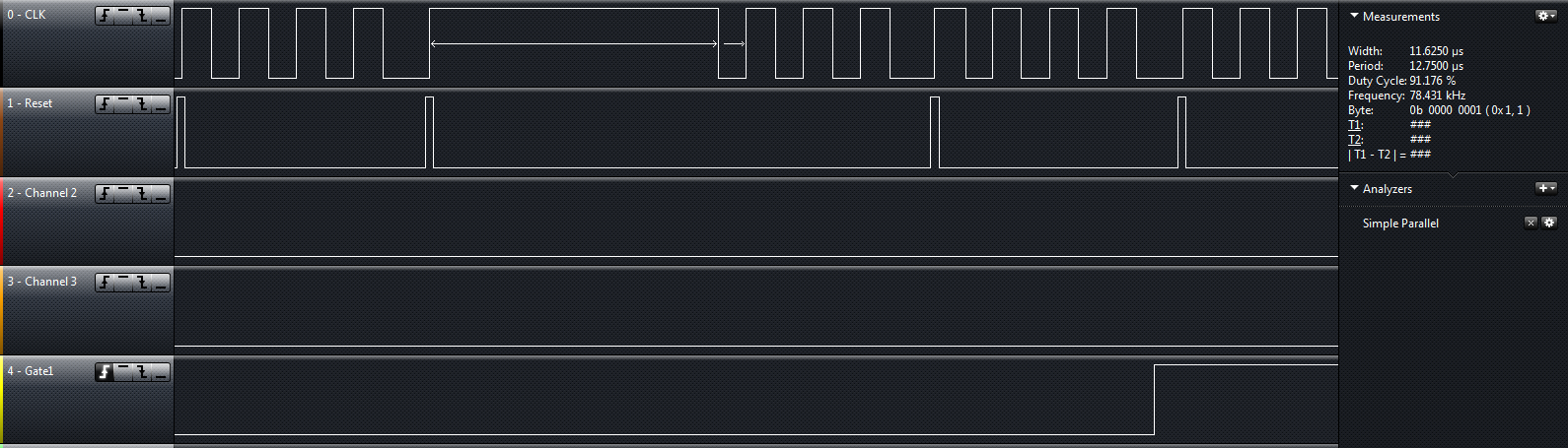
7 | * creating a CLK output for the multiplexing Working Version 0.1.10
|
8 | * creating a RESET output when the first Voice is transmitted Working Version 0.1.10
|
9 |
|
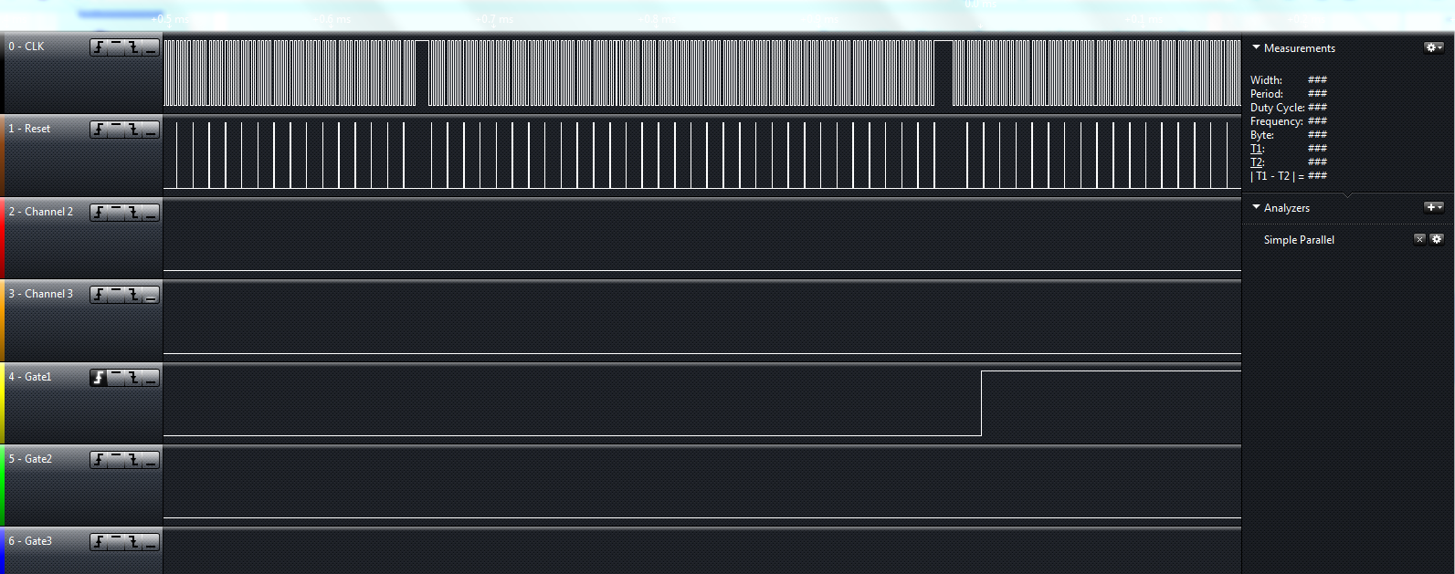
10 | * __ __ __ __ __ __ __ __
|
11 | * CLK _| |__| |__| |__| |__| |__| |__| |__| |_
|
12 |
|
13 | * Channel 1 2 3 4 5 6 7 8
|
14 | * __
|
15 | * RESET _| |____________________________________________
|
16 |
|
17 |
|
18 | * Creating the Output for the Octave Voltage
|
19 | * Creating the Output for the Key Voltage
|
20 |
|
21 | * Creating the (monophonic) Aftertouch Voltage with the internal PWM
|
22 | * Creating the Pitchbend Voltage with internal PWM
|
23 | * Creating the Mod wheel Voltage with internal PWM
|
24 |
|
25 |
|
26 |
|
27 | * Author: Oliver Fischhaupt
|
28 | * Created:16.05.2014
|
29 | * Version 0.1.10
|
30 | */
|
31 |
|
32 |
|
33 | #include <avr/io.h>
|
34 | #include <stdlib.h>
|
35 | #include <avr/interrupt.h>
|
36 |
|
37 | #ifndef F_CPU
|
38 | #define F_CPU 16000000UL
|
39 | #endif
|
40 |
|
41 |
|
42 | #define BAUD 31250UL // Baudrate
|
43 |
|
44 | // Calculating the Baudrate
|
45 | #define UBRR_VAL ((F_CPU+BAUD*8)/(BAUD*16)-1) // Rounding
|
46 | #define BAUD_REAL (F_CPU/(16*(UBRR_VAL+1))) // Real Baudrate
|
47 | #define BAUD_ERROR ((BAUD_REAL*1000)/BAUD) // Calculating the Error in Promille, 1000 = NoError.
|
48 |
|
49 | #if ((BAUD_ERROR<990) || (BAUD_ERROR>1010))
|
50 | #error Error in Baudrate is larger 1% !
|
51 | #endif
|
52 |
|
53 |
|
54 | #define NUM_VOICES 4 // Number of Voices
|
55 | #define MIDI_CHANNEL 0 // MIDI Channel
|
56 |
|
57 | #define LOW 0
|
58 | #define HIGH 1
|
59 |
|
60 | // MIDI Messages
|
61 | #define NOTE_ON 0x90 // Midi note on message
|
62 | #define NOTE_OFF 0x80 // Midi note off message
|
63 | #define PITCH 0xE0 // pitch bender (Not Implemented yet)
|
64 | #define AFTERTOUCH 0xD0 // after touch command (Not Implemented yet)
|
65 | #define CC 0xB0 // Continuous Controller (Not Implemented yet)
|
66 | #define CHAN_PRES 0xD0 // Channel Pressure (Not Implemented yet)
|
67 |
|
68 |
|
69 | void init_USART(void)
|
70 | {
|
71 | UCSR3B |= 0x08; //UART TX (Transmit enable)
|
72 | UCSR3B |= 0x10; //UART RX (Receive enable)
|
73 | UCSR3B |= 0x80; //RX Interrupt enable
|
74 | UCSR3C |= 0x00; //Mode Async 8N1 (8 Databits, No Parity, 1 Stopbit)
|
75 | UCSR3C |= 0x04;
|
76 | UCSR3C |= 0x02;
|
77 | UCSR3A = 0x00;
|
78 |
|
79 | UBRR3H = 0; //Highbyte is 0
|
80 | UBRR3L = UBRR_VAL; //Lowbyte
|
81 | }
|
82 |
|
83 |
|
84 | volatile unsigned char action = 2; //0 =note off ; 1=note on ; 2= nothing
|
85 | volatile unsigned char key = 0 ;
|
86 | volatile unsigned char velocity = 0;
|
87 |
|
88 | volatile unsigned char voice = 0;
|
89 | volatile unsigned char lastVoice = 0;
|
90 | volatile unsigned char nextVoice = 0;
|
91 |
|
92 | // ARRAYS for GATES and used Voices
|
93 | volatile unsigned char voices [] = {LOW,LOW,LOW,LOW,LOW,LOW,LOW,LOW};
|
94 | volatile uint8_t gates [] = {LOW,LOW,LOW,LOW,LOW,LOW,LOW,LOW};
|
95 |
|
96 |
|
97 |
|
98 | // DECIMAL to BINARY NOT USED
|
99 | unsigned char voiceCounter1 [] = {LOW,HIGH,LOW,HIGH,LOW,HIGH,LOW,HIGH};
|
100 | unsigned char voiceCounter2 [] = {LOW,LOW,HIGH,HIGH,LOW,LOW,HIGH,HIGH};
|
101 | unsigned char voiceCounter4 [] = {LOW,LOW,LOW,LOW,HIGH,HIGH,HIGH,HIGH};
|
102 |
|
103 | /*Port Mapping Arduino MEGA2560 Board
|
104 |
|
105 | PORTB Gate Output
|
106 | Pin Name Mapped Pin Name Function
|
107 | PB0 Digital Pin53 GATE 1
|
108 | PB1 Digital Pin52 GATE 2
|
109 | PB2 Digital Pin51 GATE 3
|
110 | PB3 Digital Pin50 GATE 4
|
111 | PB4 Digital Pin10 GATE 5
|
112 | PB5 Digital Pin11 GATE 6
|
113 | PB6 Digital Pin12 GATE 7
|
114 | PB7 Digital Pin13 GATE 8
|
115 |
|
116 | PORTA Note Output
|
117 | Pin Name Mapped Pin Name Function
|
118 | PA0 Digital Pin22 LOW NOTEA
|
119 | PA1 Digital Pin23 LOW NOTEB
|
120 | PA2 Digital Pin24 LOW NOTEC
|
121 | PA3 Digital Pin25 HIGH NOTEA
|
122 | PA4 Digital Pin26 HIGH NOTEB
|
123 | PA5 Digital Pin27 HIGH NOTEC
|
124 | PA6 Digital Pin28 LOW CS
|
125 | PA7 Digital Pin29 HIGH CS
|
126 |
|
127 | PORTC OCT Output, CLK and Reset
|
128 | Pin Name Mapped Pin Name Function
|
129 | PC0 Digital Pin37 OCTA
|
130 | PC1 Digital Pin36 OCTB
|
131 | PC2 Digital Pin35 OCTC
|
132 | PC3 Digital Pin34 OCT CS
|
133 | PC4 Digital Pin33 CLK
|
134 | PC5 Digital Pin32 RESET
|
135 | PC6 Digital Pin31 NA
|
136 | PC7 Digital Pin30 NA
|
137 |
|
138 | */
|
139 |
|
140 | void noteOff(unsigned char channel, unsigned char pitch, unsigned char velocity)
|
141 | {
|
142 | for(int i = 0 ;i < NUM_VOICES;i++)
|
143 | {
|
144 | if(voices [i] == pitch)
|
145 | {
|
146 | gates[i] = LOW;
|
147 | }
|
148 | }
|
149 | }
|
150 |
|
151 | void noteOn(unsigned char channel, unsigned char pitch, unsigned char velocity)
|
152 | {
|
153 | if (velocity == 0 )
|
154 | {
|
155 | noteOff(channel, pitch, velocity );
|
156 | }
|
157 | else
|
158 | {
|
159 | gates[nextVoice] = HIGH;
|
160 | voices [nextVoice]= pitch;
|
161 | nextVoice++;
|
162 |
|
163 | if(nextVoice ==NUM_VOICES)
|
164 | {
|
165 | nextVoice = 0;
|
166 | }
|
167 | }
|
168 | }
|
169 |
|
170 |
|
171 | int main(int argc, char **argv) {
|
172 | init_USART();
|
173 |
|
174 | DDRA = (1 << PA0) | (1 << PA1) | (1 << PA2) | (1 << PA3) | (1 << PA4) | (1 << PA5) | (1 << PA6) | (1 << PA7);
|
175 | DDRB = (1 << PB0) | (1 << PB1) | (1 << PB2) | (1 << PB3) | (1 << PB4) | (1 << PB5) | (1 << PB6) | (1 << PB7); // PB7 an PORTB als Ausgang setzen
|
176 | DDRC = (1 << PC0) | (1 << PC1) | (1 << PC2) | (1 << PC3) | (1 << PC4) | (1 << PC5);
|
177 |
|
178 | sei();
|
179 | while (1)
|
180 | {
|
181 | uint8_t tmp = 0;
|
182 | for(voice = 0 ;voice < NUM_VOICES ;voice++)
|
183 | {
|
184 | if(voice ==0)
|
185 | {
|
186 | PORTC |= (1<<PC5); //Generating the Reset Signal High
|
187 |
|
188 | }
|
189 | PORTC ^= (1<<PC4); //Generating the Clock Signal
|
190 | PORTC &= ~ (1<<PC5); //Generating the Reset Signal Low
|
191 |
|
192 | PORTA = key; //output Key NOT IMPLEMENTED
|
193 |
|
194 |
|
195 | tmp >>= 1;
|
196 | if( gates[voice] == HIGH)
|
197 | {
|
198 |
|
199 | tmp |= (1 << 7);
|
200 | }
|
201 |
|
202 | PORTC ^= (1<<PC4); //Generating the Clock Signal
|
203 |
|
204 |
|
205 |
|
206 | //TODO
|
207 | //CS Octave
|
208 | //Octave Output
|
209 | //CS Note
|
210 | //Note Output
|
211 | }
|
212 | PORTB = tmp; //GATE Output
|
213 |
|
214 |
|
215 | }
|
216 | }
|
217 |
|
218 |
|
219 |
|
220 |
|
221 | #define FRAMING_ERROR (1<<FE3)
|
222 | #define PARITY_ERROR (1<<UPE3)
|
223 | #define DATA_OVERRUN (1<<DOR3)
|
224 |
|
225 | ISR(USART3_RX_vect)
|
226 | {
|
227 | unsigned char status,byte;
|
228 | status = UCSR3A;
|
229 | byte = UDR3;
|
230 |
|
231 | if ((status & (FRAMING_ERROR | PARITY_ERROR | DATA_OVERRUN))==0 )
|
232 | {
|
233 | if (byte == NOTE_ON)
|
234 | {
|
235 | action = 1;
|
236 | }
|
237 | else if (byte == NOTE_OFF)
|
238 | {
|
239 | action = 0;
|
240 | }
|
241 | else if (byte == AFTERTOUCH)
|
242 | {
|
243 | //TO BE IMPLEMENTED
|
244 | }
|
245 | else if ((action==0)&&(key==0) )
|
246 | { // if we received a "note off", we wait for which note (databyte)
|
247 | key=byte;
|
248 | noteOff(1,key,0);
|
249 | key=0;
|
250 | velocity=0;
|
251 | action=2;
|
252 | }
|
253 | else if ( (action==1)&&(key==0) )
|
254 | { // if we received a "note on", we wait for the note (databyte)
|
255 | key=byte;
|
256 | }
|
257 | else if ( (action==1)&&(key!=0) )
|
258 | { // ...and then the velocity
|
259 | velocity=byte;
|
260 | noteOn(1,key,velocity);
|
261 | key=0;
|
262 | velocity=0;
|
263 | action=0;
|
264 | }
|
265 | }
|
266 | }
|