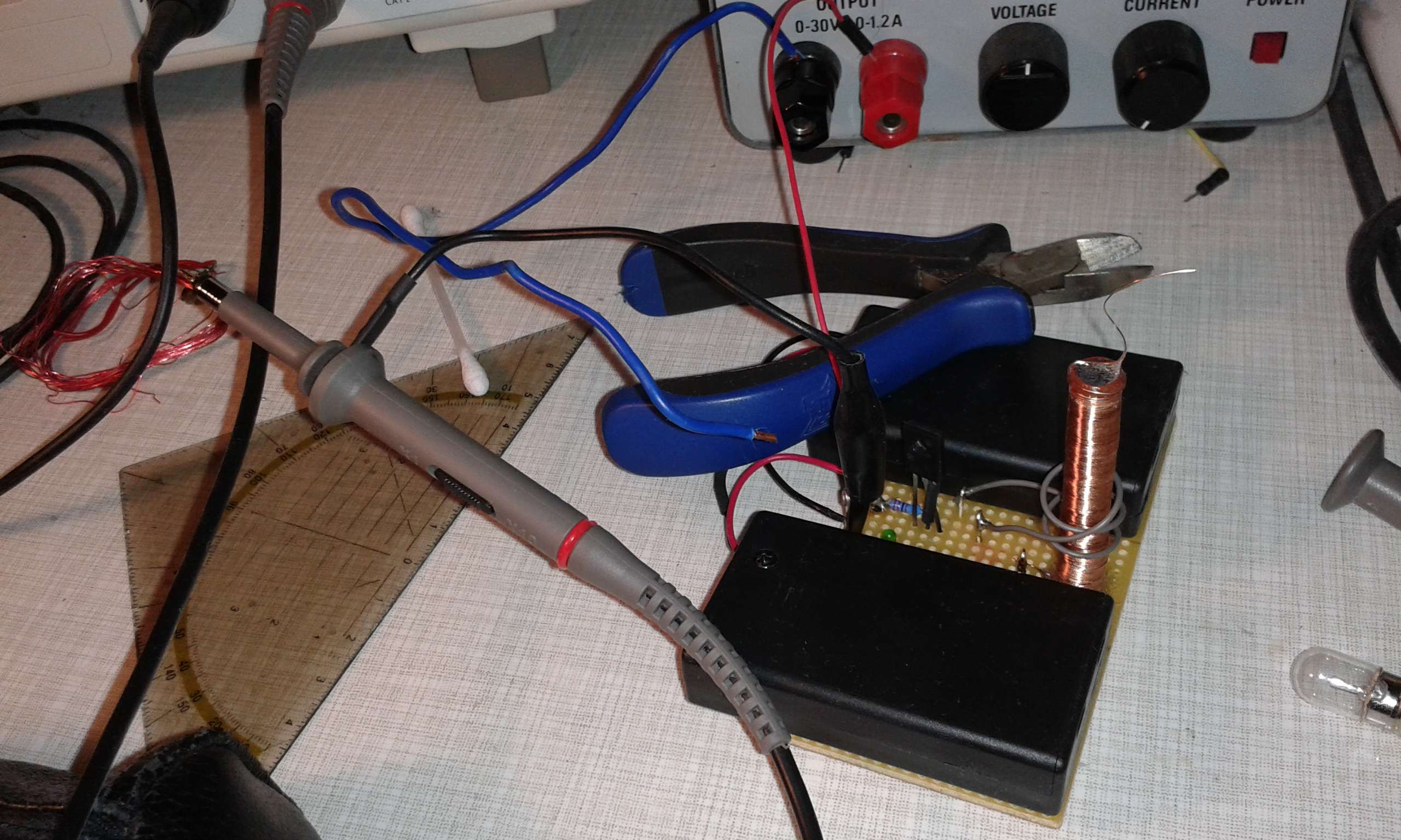
Hallo,

ich wollte die Miniaturteslaspule aus, die in dem folgenden
heise-Artikel referenziert wird nachbauen.

http://www.heise.de/newsticker/meldung/Mini-Teslaspule-mit-9-Volt-Batterie-2506409.html

Ich verwende statt des
Transistors 2222A einen BC338 bzw. einen BD139
Den Ferritkern hab ich mir aus einem alten Empfangsmodule für DCF-77
genommen und ca. 275 Windungen Kupferlackdraht 0,2mm² drummgewickelt.

Ich nutze zunächst eine Labornetztgerät bis 1A einstellbar bis 30V.
Später 6 mal 1,5V AAA Batterien.

ich hab hier eine alte Fahrradlampe ca. 9V drangehalten wie im Video
doch nichts leuchtet oder glimmt!?

Am Collector des Transistors messe ich eine Wechselspannung bis mit
maximale Amplitude von 8V mit einem Gleichspannungsoffset.

Die Frequenz liegt bei ca. 1,5MHz.


Wie genau funktioniert die Schaltung denn?
Ohne das zu wissen ist das debuggen eher schwierig!

VG
Angehängte Dateien:
-

2014-12-28_20.42.50.jpg
350 KB
Wie original geschrieben steht:
------THEORY OF OPERATION------

-   5 to 18 volts is fed into the circuit, a resistor (R1) is placed
before the Base pin of the transistor in order to limit the amount of
current the pin receives. If too much current is allowed into the Base
pin the transistor can produce excessive heat and fail.

-   One end of the secondary (L2) is connected to the Base pin of the
transistor in order to feed it with oscillations. The two diodes (D1 and
D2) prevent the oscillations from going directly to ground. (Learn more
about oscillations and why they're important, below).

-   The transistor is made up of three pins: the Collector, the Emitter,
and the Base. If you were to think of the transistor as a garden hose
spigot (See picture 2), the Collector would be the reservoir of water.
The Emitter would be the hose and the Base would be the valve that would
allow water from the reservoir (Collector) to the hose (Emitter). The
valve (Base) is in the closed position (no water flowing) until it is
given a little nudge. When it receives a nudge, the valve opens and a
lot of water is allowed to flow from the reservoir through the hose as
long as the valve is still getting a nudge. However, as soon as the
nudge goes away the valve will close, cutting off the water from the
reservoir to the hose until the valve gets another nudge.

-   When the Base receives a little bit of current, it closes the
circuit and electricity is allowed to flow through the primary coil
(L1). However, electricity likes to take the path of least resistance so
when the electricity is allowed to flow from the collector to the
emitter (~0 ohm resistance) it will stop flowing to the base because
there is 47,000 ohms of resistance there. When the electricity stops
flowing to the base, the base will open up the circuit again until the
resistor offers less resistance than the Collector-Emitter path. This
cycle repeats itself many times a second.

-   The primary coil collapses when the electricity stops flowing
through it, when this happens, the secondary coil picks up the magnetic
field and converts it back into voltage which gets stepped up to around
a thousand volts in the process. The top load acts as a capacitor and
increases the output from the secondary causing electrons in the air to
become excited.

-   Finally, the oscillations from the secondary coil are fed back into
the transistor in order to 'tune' or achieve maximum output from the
Slayer Exciter.
Ich hab mir jetzt mal eine LED an 15 Wicklungen Kupferlackdraht gelötet
und siehe da die LED leuchtet in erqickendem grün.
hat das mit den Kompaktleuchtstofflampen Aussicht auf Erfolg?
Hab leider gerad keine zur Hand.

Nun Gut allen hier vielen Dank.
Jetzt spiel ich noch ein bisschen rum.
Aussicht auf Erfolg wirst Du nur haben, wenn Primär- und Sekundärkreis
IN RESONANZ schwingen, also die gleiche Resonanzfrequenz haben. Ob die
Teslaspule elektronisch angesteuert wird oder auf traditionelle Weise,
ist dafür unerheblich. Eine Teslaspule richtig abzugleichen, kann
einiges an Arbeit bedeuten. Ich habe damals für meine Teslaspule (ca 30
cm Höhe) ein paar Tage (mit Unterbrechung) gebraucht, der Aufwand hat
sich allerdings gelohnt.
Übrigens:
Die Elektronik bei Lampen mit elektronischem Vorschaltgerät (auch Deine
Kompakt-Leuchtstofflampen) können durch Einwirkung der Spannung zerstört
werden!
Jesus sein Papa schrieb:
> IN RESONANZ

Wozu Resonanz? Die Spule hat einen

Der Kribbler schrieb:
> Ferritkern

,und ist deshalb gar keine Teslaspule. Ein ganz simpler HV-Trafo, den
man sogar deutlich besser aufbauen könnte. Vor allem größer, macht den
selben Aufwand, aber mehr Spaß.
> Ein ganz simpler HV-Trafo ...  mehr Spaß.

Jo, zum Beispiel eine KFZ Zündspule angesteuert von einem Relais das als
Summer beschaltet ist. Braucht neben der Batterie nur zwei Bauteile und
die bekommt man beide beim Schrotthändler.
Bitte melde dich an um einen Beitrag zu schreiben. Anmeldung ist kostenlos und dauert nur eine Minute.
Bestehender Account
Schon ein Account bei Google/GoogleMail? Keine Anmeldung erforderlich!
Mit Google-Account einloggen
Mit Google-Account einloggen
Noch kein Account? Hier anmelden.