1 | #ifndef LCD_H
|
2 | #define LCD_H
|
3 | ...
|
4 | #include <inttypes.h>
|
5 | #include <avr/pgmspace.h>
|
6 |
|
7 | #if (__GNUC__ * 100 + __GNUC_MINOR__) < 405
|
8 | #error "This library requires AVR-GCC 4.5 or later, update to newer AVR-GCC compiler !"
|
9 | #endif
|
10 |
|
11 |
|
12 | /**@{*/
|
13 |
|
14 | /*
|
15 | * LCD and target specific definitions below can be defined in a separate include file with name lcd_definitions.h instead modifying this file
|
16 | * by adding -D_LCD_DEFINITIONS_FILE to the CDEFS section in the Makefile
|
17 | * All definitions added to the file lcd_definitions.h will override the default definitions from lcd.h
|
18 | */
|
19 | #ifdef _LCD_DEFINITIONS_FILE
|
20 | #include "lcd_definitions.h"
|
21 | #endif
|
22 |
|
23 |
|
24 | /**
|
25 | * @name Definition for LCD controller type
|
26 | * Use 0 for HD44780 controller, change to 1 for displays with KS0073 controller.
|
27 | */
|
28 | #ifndef LCD_CONTROLLER_KS0073
|
29 | #define LCD_CONTROLLER_KS0073 0 /**< Use 0 for HD44780 controller, 1 for KS0073 controller */
|
30 | #endif
|
31 |
|
32 | /**
|
33 | * @name Definitions for Display Size
|
34 | * Change these definitions to adapt setting to your display
|
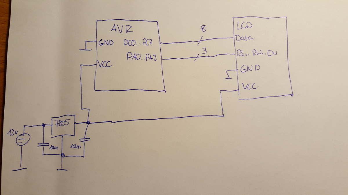
35 | *
|
36 | * These definitions can be defined in a separate include file \b lcd_definitions.h instead modifying this file by
|
37 | * adding -D_LCD_DEFINITIONS_FILE to the CDEFS section in the Makefile.
|
38 | * All definitions added to the file lcd_definitions.h will override the default definitions from lcd.h
|
39 | *
|
40 | */
|
41 | #ifndef LCD_LINES
|
42 | #define LCD_LINES 2 /**< number of visible lines of the display */
|
43 | #endif
|
44 | #ifndef LCD_DISP_LENGTH
|
45 | #define LCD_DISP_LENGTH 16 /**< visibles characters per line of the display */
|
46 | #endif
|
47 | #ifndef LCD_LINE_LENGTH
|
48 | #define LCD_LINE_LENGTH 0x40 /**< internal line length of the display */
|
49 | #endif
|
50 | #ifndef LCD_START_LINE1
|
51 | #define LCD_START_LINE1 0x00 /**< DDRAM address of first char of line 1 */
|
52 | #endif
|
53 | #ifndef LCD_START_LINE2
|
54 | #define LCD_START_LINE2 0x40 /**< DDRAM address of first char of line 2 */
|
55 | #endif
|
56 | #ifndef LCD_START_LINE3
|
57 | #define LCD_START_LINE3 0x14 /**< DDRAM address of first char of line 3 */
|
58 | #endif
|
59 | #ifndef LCD_START_LINE4
|
60 | #define LCD_START_LINE4 0x54 /**< DDRAM address of first char of line 4 */
|
61 | #endif
|
62 | #ifndef LCD_WRAP_LINES
|
63 | #define LCD_WRAP_LINES 0 /**< 0: no wrap, 1: wrap at end of visibile line */
|
64 | #endif
|
65 |
|
66 |
|
67 | /**
|
68 | * @name Definitions for 4-bit IO mode
|
69 | *
|
70 | * The four LCD data lines and the three control lines RS, RW, E can be on the
|
71 | * same port or on different ports.
|
72 | * Change LCD_RS_PORT, LCD_RW_PORT, LCD_E_PORT if you want the control lines on
|
73 | * different ports.
|
74 | *
|
75 | * Normally the four data lines should be mapped to bit 0..3 on one port, but it
|
76 | * is possible to connect these data lines in different order or even on different
|
77 | * ports by adapting the LCD_DATAx_PORT and LCD_DATAx_PIN definitions.
|
78 | *
|
79 | * Adjust these definitions to your target.\n
|
80 | * These definitions can be defined in a separate include file \b lcd_definitions.h instead modifying this file by
|
81 | * adding \b -D_LCD_DEFINITIONS_FILE to the \b CDEFS section in the Makefile.
|
82 | * All definitions added to the file lcd_definitions.h will override the default definitions from lcd.h
|
83 | *
|
84 | */
|
85 | #define LCD_IO_MODE 1 /**< 0: memory mapped mode, 1: IO port mode */
|
86 |
|
87 | #if LCD_IO_MODE
|
88 |
|
89 | #ifndef LCD_PORT
|
90 | #define LCD_PORT PORTC /**< port for the LCD lines */
|
91 | #endif
|
92 | #ifndef LCD_DATA0_PORT
|
93 | #define LCD_DATA0_PORT LCD_PORT /**< port for 4bit data bit 0 */
|
94 | #endif
|
95 | #ifndef LCD_DATA1_PORT
|
96 | #define LCD_DATA1_PORT LCD_PORT /**< port for 4bit data bit 1 */
|
97 | #endif
|
98 | #ifndef LCD_DATA2_PORT
|
99 | #define LCD_DATA2_PORT LCD_PORT /**< port for 4bit data bit 2 */
|
100 | #endif
|
101 | #ifndef LCD_DATA3_PORT
|
102 | #define LCD_DATA3_PORT LCD_PORT /**< port for 4bit data bit 3 */
|
103 | #endif
|
104 | #ifndef LCD_DATA0_PIN
|
105 | #define LCD_DATA0_PIN 0 /**< pin for 4bit data bit 0 */
|
106 | #endif
|
107 | #ifndef LCD_DATA1_PIN
|
108 | #define LCD_DATA1_PIN 1 /**< pin for 4bit data bit 1 */
|
109 | #endif
|
110 | #ifndef LCD_DATA2_PIN
|
111 | #define LCD_DATA2_PIN 2 /**< pin for 4bit data bit 2 */
|
112 | #endif
|
113 | #ifndef LCD_DATA3_PIN
|
114 | #define LCD_DATA3_PIN 3 /**< pin for 4bit data bit 3 */
|
115 | #endif
|
116 | #ifndef LCD_RS_PORT
|
117 | #define LCD_RS_PORT LCD_PORT /**< port for RS line */
|
118 | #endif
|
119 | #ifndef LCD_RS_PIN
|
120 | #define LCD_RS_PIN 4 /**< pin for RS line */
|
121 | #endif
|
122 | #ifndef LCD_RW_PORT
|
123 | #define LCD_RW_PORT LCD_PORT /**< port for RW line */
|
124 | #endif
|
125 | #ifndef LCD_RW_PIN
|
126 | #define LCD_RW_PIN 5 /**< pin for RW line */
|
127 | #endif
|
128 | #ifndef LCD_E_PORT
|
129 | #define LCD_E_PORT LCD_PORT /**< port for Enable line */
|
130 | #endif
|
131 | #ifndef LCD_E_PIN
|
132 | #define LCD_E_PIN 6 /**< pin for Enable line */
|
133 | #endif
|
134 |
|
135 | #elif defined(__AVR_AT90S4414__) || defined(__AVR_AT90S8515__) || defined(__AVR_ATmega64__) || \
|
136 | defined(__AVR_ATmega8515__)|| defined(__AVR_ATmega103__) || defined(__AVR_ATmega128__) || \
|
137 | defined(__AVR_ATmega161__) || defined(__AVR_ATmega162__)
|
138 | /*
|
139 | * memory mapped mode is only supported when the device has an external data memory interface
|
140 | */
|
141 | #define LCD_IO_DATA 0xC000 /* A15=E=1, A14=RS=1 */
|
142 | #define LCD_IO_FUNCTION 0x8000 /* A15=E=1, A14=RS=0 */
|
143 | #define LCD_IO_READ 0x0100 /* A8 =R/W=1 (R/W: 1=Read, 0=Write */
|
144 |
|
145 | #else
|
146 | #error "external data memory interface not available for this device, use 4-bit IO port mode"
|
147 |
|
148 | #endif
|
149 |
|
150 |
|
151 | /**
|
152 | * @name Definitions of delays
|
153 | * Used to calculate delay timers.
|
154 | * Adapt the F_CPU define in the Makefile to the clock frequency in Hz of your target
|
155 | *
|
156 | * These delay times can be adjusted, if some displays require different delays.\n
|
157 | * These definitions can be defined in a separate include file \b lcd_definitions.h instead modifying this file by
|
158 | * adding \b -D_LCD_DEFINITIONS_FILE to the \b CDEFS section in the Makefile.
|
159 | * All definitions added to the file lcd_definitions.h will override the default definitions from lcd.h
|
160 | */
|
161 | #ifndef LCD_DELAY_BOOTUP
|
162 | #define LCD_DELAY_BOOTUP 16000 /**< delay in micro seconds after power-on */
|
163 | #endif
|
164 | #ifndef LCD_DELAY_INIT
|
165 | #define LCD_DELAY_INIT 5000 /**< delay in micro seconds after initialization command sent */
|
166 | #endif
|
167 | #ifndef LCD_DELAY_INIT_REP
|
168 | #define LCD_DELAY_INIT_REP 64 /**< delay in micro seconds after initialization command repeated */
|
169 | #endif
|
170 | #ifndef LCD_DELAY_INIT_4BIT
|
171 | #define LCD_DELAY_INIT_4BIT 64 /**< delay in micro seconds after setting 4-bit mode */
|
172 | #endif
|
173 | #ifndef LCD_DELAY_BUSY_FLAG
|
174 | #define LCD_DELAY_BUSY_FLAG 4 /**< time in micro seconds the address counter is updated after busy flag is cleared */
|
175 | #endif
|
176 | #ifndef LCD_DELAY_ENABLE_PULSE
|
177 | #define LCD_DELAY_ENABLE_PULSE 1 /**< enable signal pulse width in micro seconds */
|
178 | #endif
|
179 | ...
|