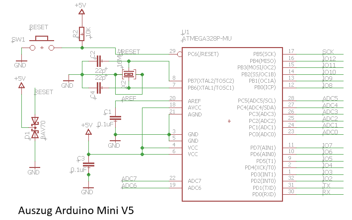
Hallo zusammen,

ich habe mir den Schaltplan vom Arduino Mini mal als Referenz geöffnet.
Hier habe ich gesehen das in der Reset Leitung eine doppel Diode BAV70
eingesetzt ist.
Ausschnitt des Plans ist im Anhang, das erstbeste Datenblatt der Diode
ist unten verlinkt.
Kann mir jemand verraten welchen Zweck dies erfüllt?!

Gruß
Mark

https://assets.nexperia.com/documents/data-sheet/BAV70_SER.pdf
Angehängte Dateien:
-

arduino_mini.PNG
8,9 KB
Mark schrieb:
> Hallo zusammen,
>
> ich habe mir den Schaltplan vom Arduino Mini mal als Referenz geöffnet.
> Hier habe ich gesehen das in der Reset Leitung eine doppel Diode BAV70
> eingesetzt ist.
> Ausschnitt des Plans ist im Anhang, das erstbeste Datenblatt der Diode
> ist unten verlinkt.
> Kann mir jemand verraten welchen Zweck dies erfüllt?!
>
> Gruß
> Mark
>
> https://assets.nexperia.com/documents/data-sheet/BAV70_SER.pdf

Denk mal nach was mit der Ladung in dem reset-C passiert wenn die 5V
zusammenbrechen und welche Auswirkungen das auf den Chip haben könnte -
sowohl als auch.
http://forum.arduino.cc/index.php?topic=86389.0

The change was to add a diode wired from +5vdc to the reset pin, cathode
to +5vdc. The prior auto-reset wiring design could cause an intermittent
latch-up problem when auto-reset was activated. This 'latch-up' problem
could effect most  prior arduino boards, not just the Uno boards, but
was a little more prevalent when the Uno R2 design added a pull-down
resistor on the 8u2 reset signal line. We never did find out why they
added that resistor in the R2 design. Didn't really matter because we
could duplicate the symptom on boards prior to R2, just not as
frequently. There was a long post on this forum about this problem and I
spend some time with others helping to try and verify if it was a real
problem or not. It was real but pretty difficult to demonstrate in a
repeatable manner. The problem was that the capacitance coupled reset
pulse was sometimes triggering the arduino reset function into
activating into it's high-voltage programming mode by creating a +10vdc
pulse to the reset pin, rather then just a standard reset. Again it was
not a common fault that everyone would experience as a lot depended on
if a load was also wired to some of the I/O pins, like a pull-up or
pull-down resistor, I forget which and which pins were most likely to
help trigger the internal chip conditions needed to reproduce to the
symptom.
Bitte melde dich an um einen Beitrag zu schreiben. Anmeldung ist kostenlos und dauert nur eine Minute.
Bestehender Account
Schon ein Account bei Google/GoogleMail? Keine Anmeldung erforderlich!
Mit Google-Account einloggen
Mit Google-Account einloggen
Noch kein Account? Hier anmelden.