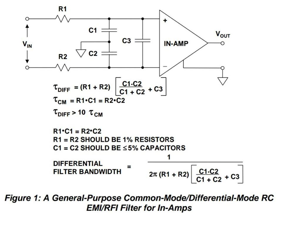
I have this long cable which is carrying two differential voltage
signals (around 300kHz maximum frequency) through a very "noisy"
environment. I need to acquire this signal through a differential op amp
(PGA204) and I was thinking about putting a filter at the input of the
instrumentation OP AMP(to know more about operational amplifier:
http://www.apogeeweb.net/article/60.html).

I found this nice filter:
See attachment iGS1m.jpg

But I cannot deeply understand the purpose of the two different filters
(DM and CM). From what I know, a common-mode noise is a noise present in
both lines with the same "polarity", while a differential-mode noise is
a noise which is complementary in respect to the ground in the two
lines.

What I see in the schematic are three LP filters, two of them (R1 C1 and
R2 C2) filter the signal in the two lines independently, with respect to
the ground, while the third one (R1 R2 C3) filters the whole
differential signal. But aren't we just adding poles to filter the input
signals? I mean, if I set the cutoff frequency of the two CM filters to
a certain value, these two filters will just filter the signal within
the range set. In the same way, the differential filter will just filter
the input signal within the range set.

    >How exactly do these two filters work together?
    >How can they act on different kinds of noise if they are just LP
filters?
Angehängte Dateien:
-

iGS1m.jpg
49 KB
Linda L. schrieb:
> But I cannot deeply understand the purpose of the two different filters
> (DM and CM). From what I know, a common-mode noise is a noise present in
> both lines with the same "polarity", while a differential-mode noise is
> a noise which is complementary in respect to the ground in the two
> lines.

Correct.
Therefore the C3 does not work on CM signals because there is no voltage
change above it caused by DM signals or disturbances.
On the other side C1 and C2 work on DM signals because every change of
the differential input signal will cause a current flow or a voltage
change above these Cs. But also a CM signal is affected by C1 and C2
because of the GND connection between them.

You can find that also in the equations of tau_CM and tau_DIFF.
Bitte melde dich an um einen Beitrag zu schreiben. Anmeldung ist kostenlos und dauert nur eine Minute.
Bestehender Account
Schon ein Account bei Google/GoogleMail? Keine Anmeldung erforderlich!
Mit Google-Account einloggen
Mit Google-Account einloggen
Noch kein Account? Hier anmelden.