Hallo zusammen,
aus dem folgenden Beitrag
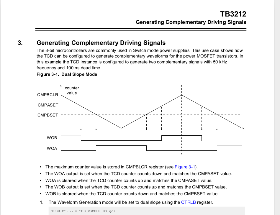
http://ww1.microchip.com/downloads/en/AppNotes/TB3212-Getting-Started-with-TCD-90003212A.pdf
habe ich den Code entnommen und mit der Änderung der Pin-Zuordnung
(TCD-WOA -> PA6, TCD-WOB -> PA7) auf einem attiny412 ausprobiert: ohne
Erfolg.
Hier der Code:
1 | #include <avr/io.h>
|
2 |
|
3 | #define SIGNAL_PERIOD_EXAMPLE_VALUE (0xC8)
|
4 | #define SIGNAL_DUTY_CYCLE_EXAMPLE_VALUE (0x64)
|
5 |
|
6 | void TCD0_init(void)
|
7 | {
|
8 | /* set the waveform mode */
|
9 | TCD0.CTRLB = TCD_WGMODE_DS_gc;
|
10 |
|
11 | /* set the signal period */
|
12 | TCD0.CMPBCLR = SIGNAL_PERIOD_EXAMPLE_VALUE;
|
13 |
|
14 | /* the signals are alternatively active and a small
|
15 | symmetric dead time is needed */
|
16 | TCD0.CMPBSET = SIGNAL_DUTY_CYCLE_EXAMPLE_VALUE + 1;
|
17 | TCD0.CMPASET = SIGNAL_DUTY_CYCLE_EXAMPLE_VALUE - 1;
|
18 |
|
19 | /* ensure ENRDY bit is set */
|
20 | while(!(TCD0.STATUS & TCD_ENRDY_bm))
|
21 | {
|
22 | ;
|
23 | }
|
24 |
|
25 | TCD0.CTRLA = TCD_CLKSEL_20MHZ_gc /* choose the timer's clock */
|
26 | | TCD_CNTPRES_DIV1_gc /* choose the prescaler */
|
27 | | TCD_ENABLE_bm; /* enable the timer */
|
28 | }
|
29 |
|
30 | void TCD0_enableOutputChannels(void)
|
31 | {
|
32 | /* enable write protected register */
|
33 | CPU_CCP = CCP_IOREG_gc;
|
34 |
|
35 | TCD0.FAULTCTRL = TCD_CMPAEN_bm /* enable channel A */
|
36 | | TCD_CMPBEN_bm; /* enable channel B */
|
37 | }
|
38 |
|
39 | void PORT_init(void)
|
40 | {
|
41 | PORTA.DIRSET = PIN6_bm /* set pin 4 as output */
|
42 | | PIN7_bm /* set pin 5 as output */
|
43 | | PIN3_bm;
|
44 | }
|
45 |
|
46 |
|
47 | int main() {
|
48 | PORT_init();
|
49 | TCD0_init();
|
50 | TCD0_enableOutputChannels();
|
51 |
|
52 | while(true) {
|
53 | PORTA.OUTTGL = PIN3_bm;
|
54 | }
|
55 | }
|
Der Code würde auch im wesentlichen dem entsprechen, was ich aus dem DB
herauslesen würde. Meine eigenen Versuche waren aber auch erfolglos.

Das togglen von PA3 dient nur zur Kontrolle, ob dies auch erreicht wird,
was auch tatsächlich ok ist. Nur an PA6 oder PA7 tut sich nichts.

Jemand eine Idee.